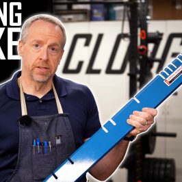
Today, we’re working on the motor mounting eccentric for the toolpost grinder. This will be part eight.
The motor is held to the spindle with a rigid aluminum clamp, and the eccentric provides a way to adjust the belt tension. Rotating the eccentric changes the distance between the motor and spindle pulleys by about four millimeters.

Turning the Outside
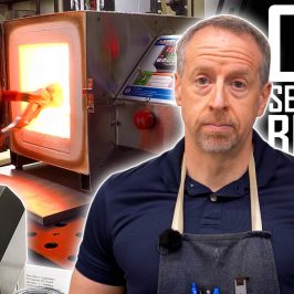
The eccentric is turned out of a piece of 3″ x 3/8″ wall DOM tubing. DOM is an acronym that stands for “drawn over mandrel.” This refers to the manufacturing process, where a flat plate is rolled into a tube, resistance welded and then drawn over a mandrel and through a die to make the inside and outside consistent and concentric. This makes the weld all but invisible.
This is different from pipe. Pipe is designed to carry fluids. Tubing is designed to be machined, welded and to carry loads.
Boring the Eccentric
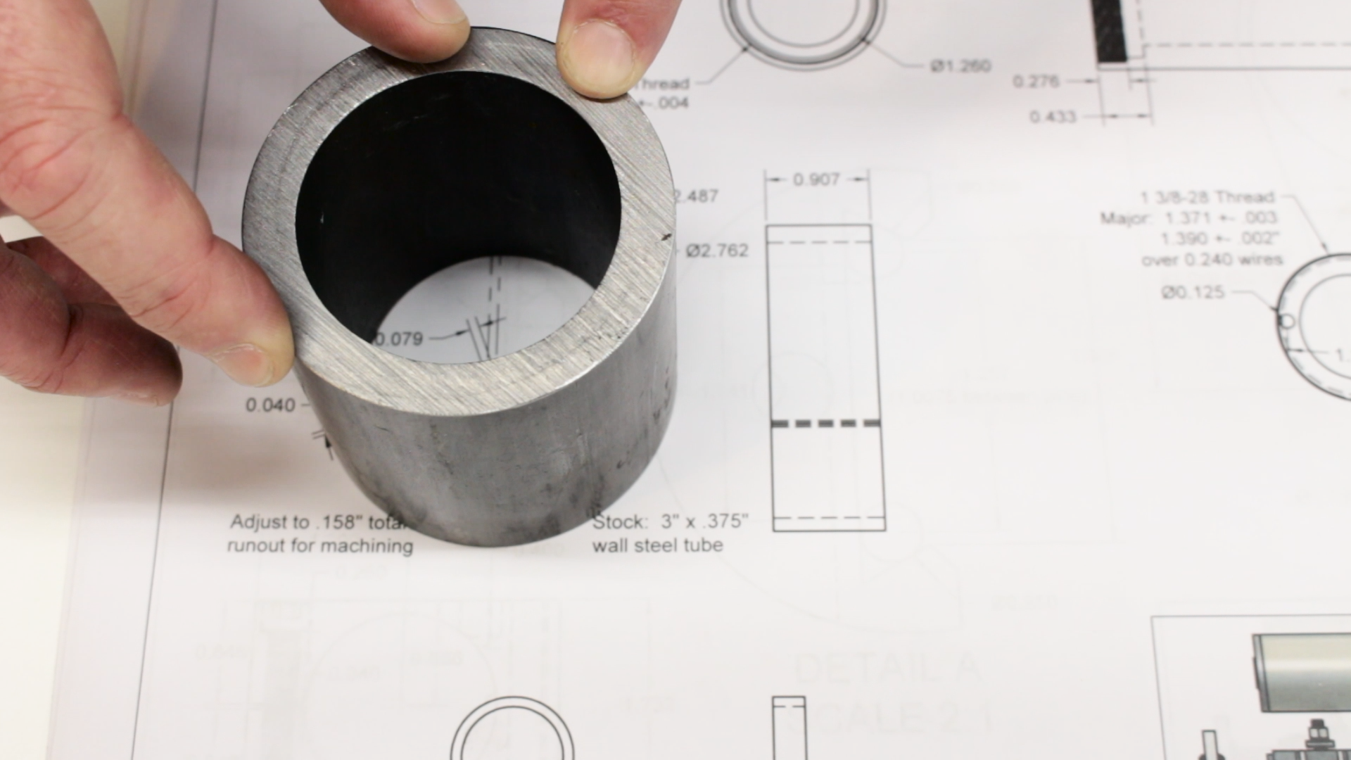
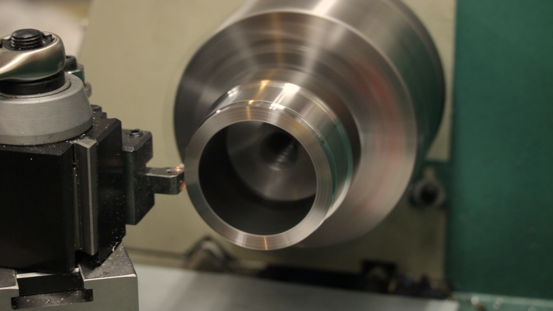
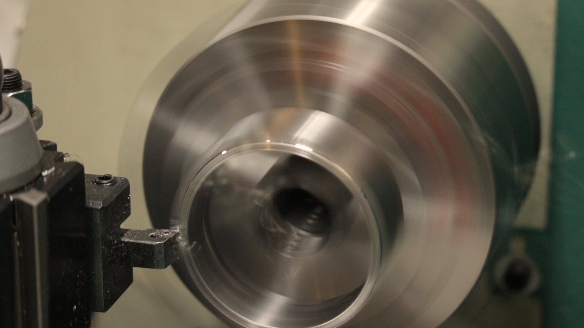
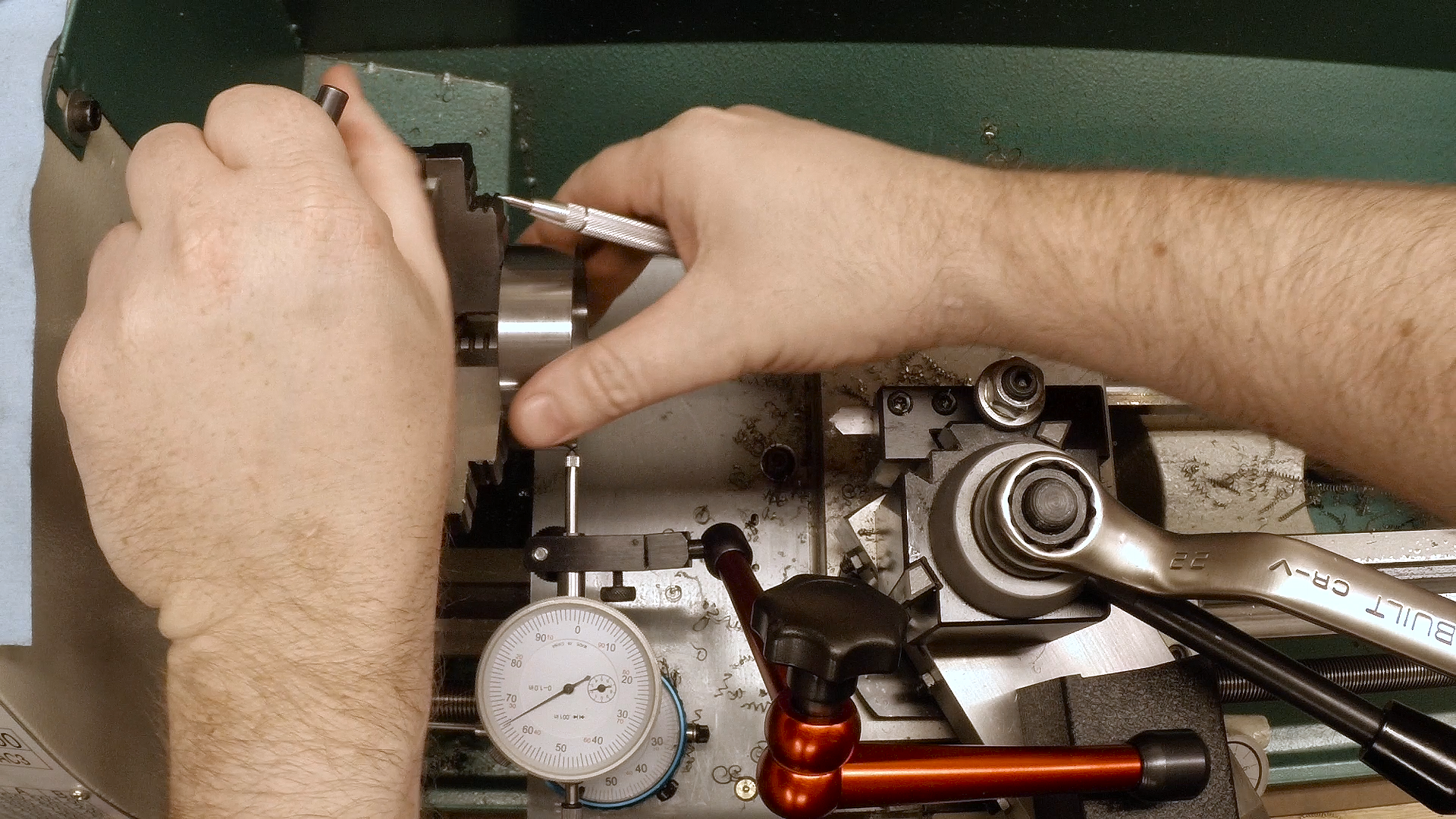
Once the outside is finished to diameter, we install the 4-jaw chuck and set the part up to run off-center in preparation to bore the inside. Using a dial indicator, we set the runout precisely. It’s important to remember that you have to reset the zero point of the dial indicator after every adjustment to the chuck jaws.

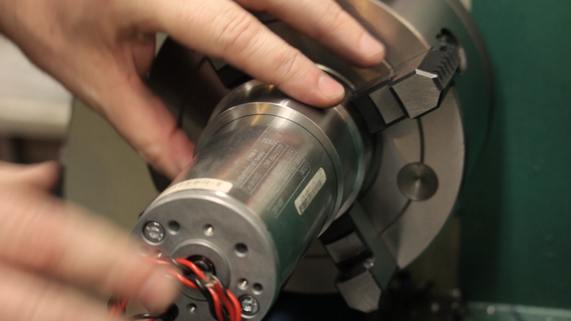
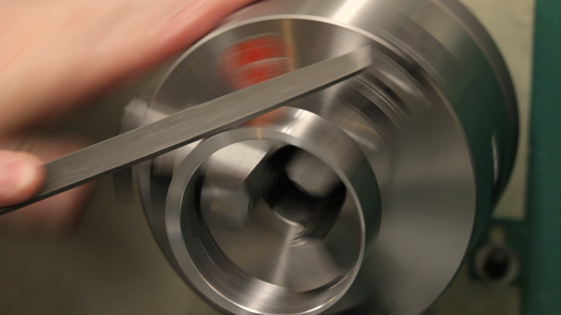
Once the part is running eccentric in the lathe, we bore out the inside to fit the motor. We remove the bulk of the material using a carbide boring bar, and then switch to high-speed steel to shave the last few thousandths. The motor fit is a difficult one because it turns out the motor isn’t actually round. It’s a few thousandths out. It was tempting to chuck the motor in the lather and fix it, but I resisted that temptation and just sized the bore for the best fit possible.
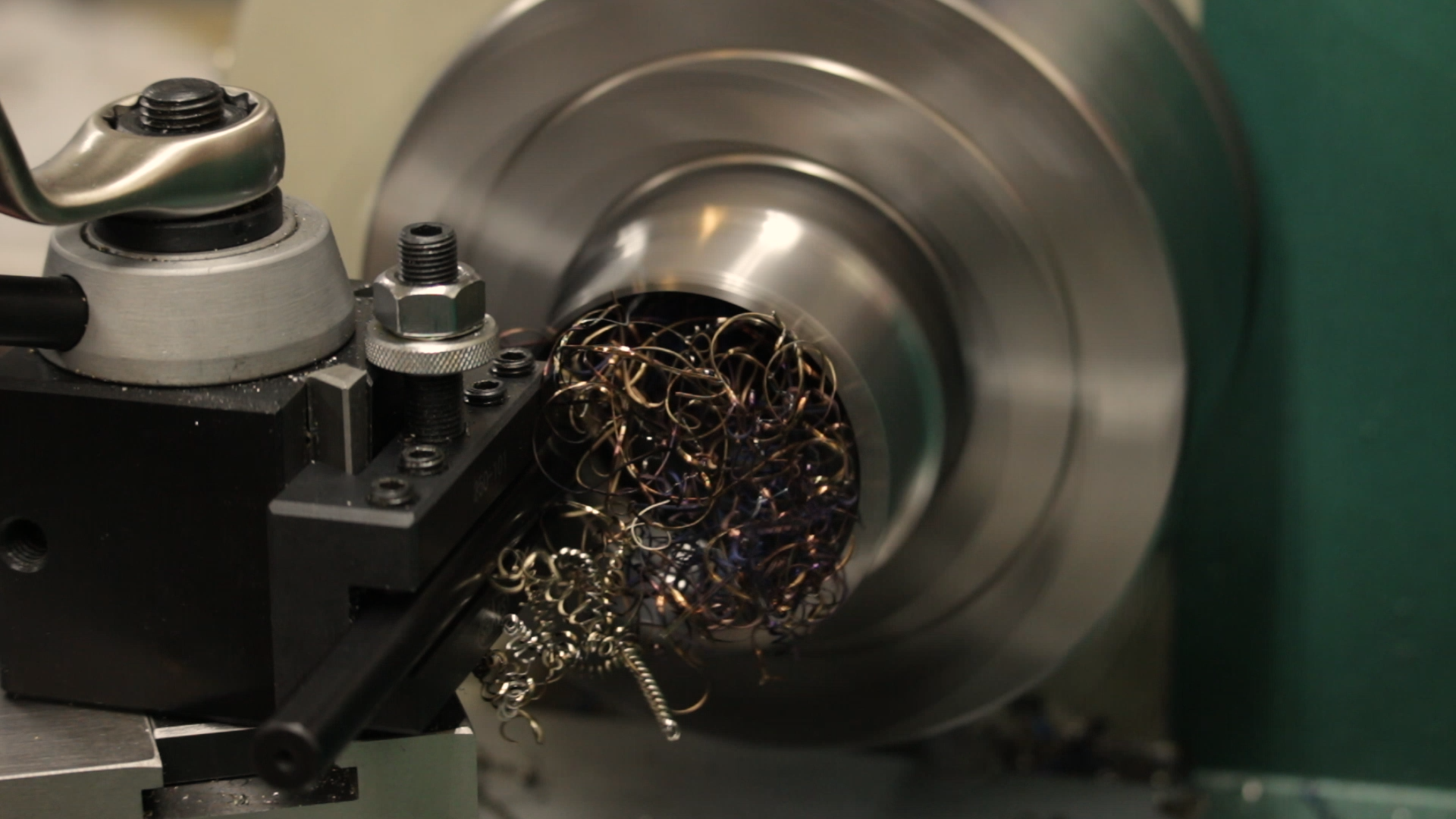
Parting Off (in the bandsaw…)
The Grizzly G0602 lathe is a great little benchtop lathe, but it isn’t super rigid. This can make parting off a challenge. After seeing how stringy the chips were when turning and knowing about the limited rigidity in the compound, I decided to cut the part off in the bandsaw.
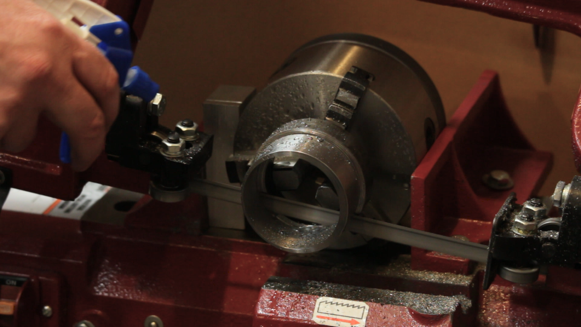
The problem was, there was only about a half inch of material to hang on to in the saw. What do we do when faced with a challenge like this? Get creative!
I ultimately chucked the part up in a 3-jaw chuck and then clamped the whole 3-jaw chuck in the bandsaw. It worked perfectly. We’ll have to add that to the list of standard setups.
Finishing Up
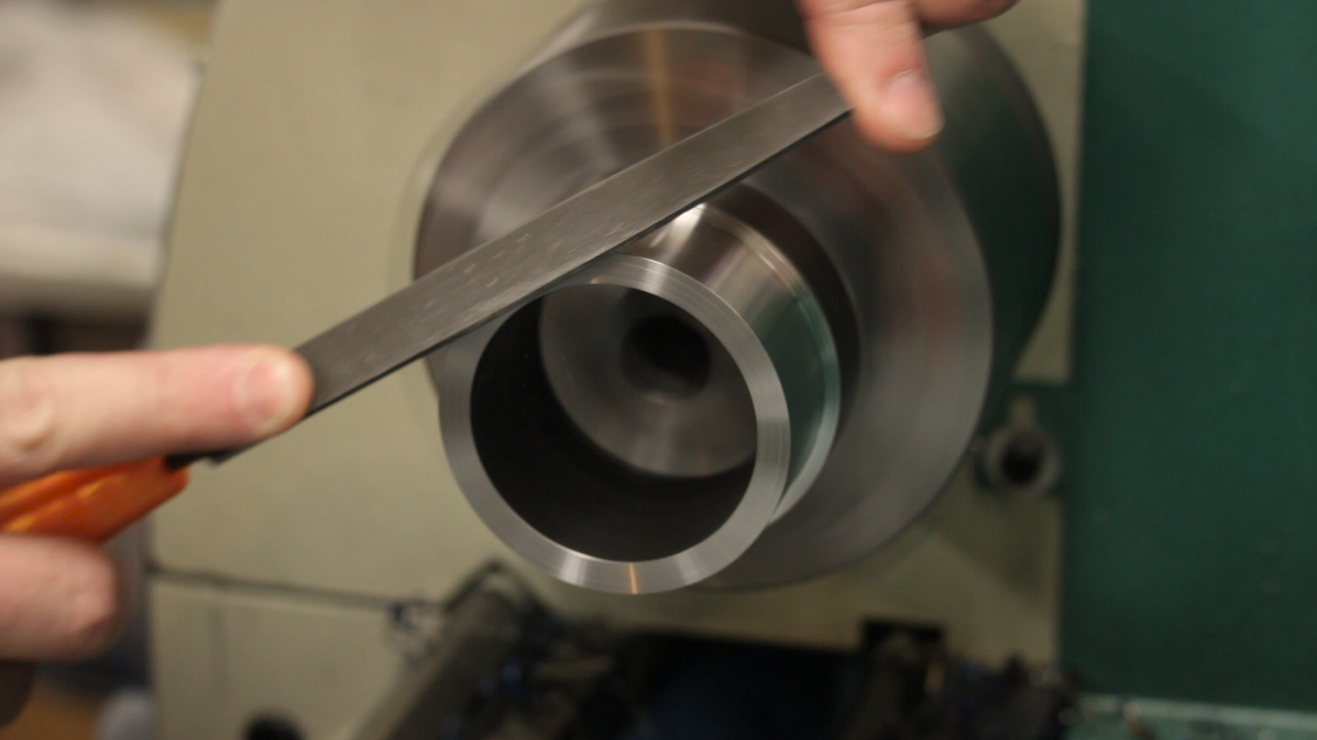
Putting the three-jaw chuck back in the lathe, we finish up by facing the part to length (or thickness in this case) and clean up the edges.
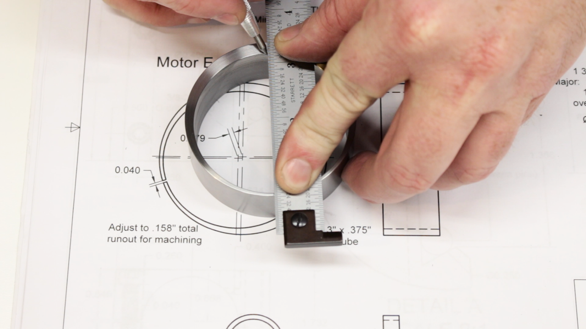
Eventually, we’ll need to split the eccentric so it can clamp around the motor, but it isn’t clear whether it will spring open or closed when it’s split, so we’ll just leave it together for now, until after we make the clamp. I did take the extra step of locating the high and low points with a dial indicator and marking them with a line for later.
That’s it for today. Next time we’ll work on the aluminum motor clamp.
If you haven’t seen the previous videos, a playlist with all of the parts of this project is here: https://www.youtube.com/playlist?list=PLDlWKv7KIIr-uFMjbe7AlsHswL6qihPPU