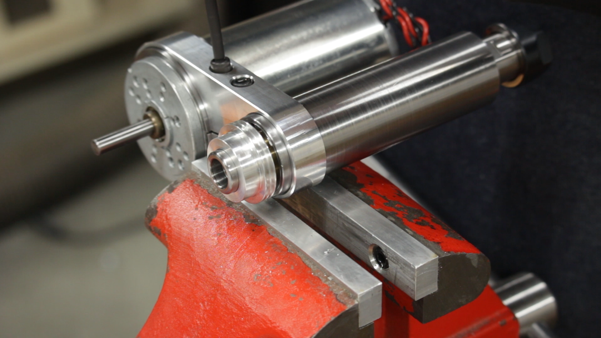
Today we’re finished the motor clamp for the toolpost grinder. We already have the body of the clamp finished. Now we just need to drill and slot it to turn it into a clamp.
Setting Up to Drill
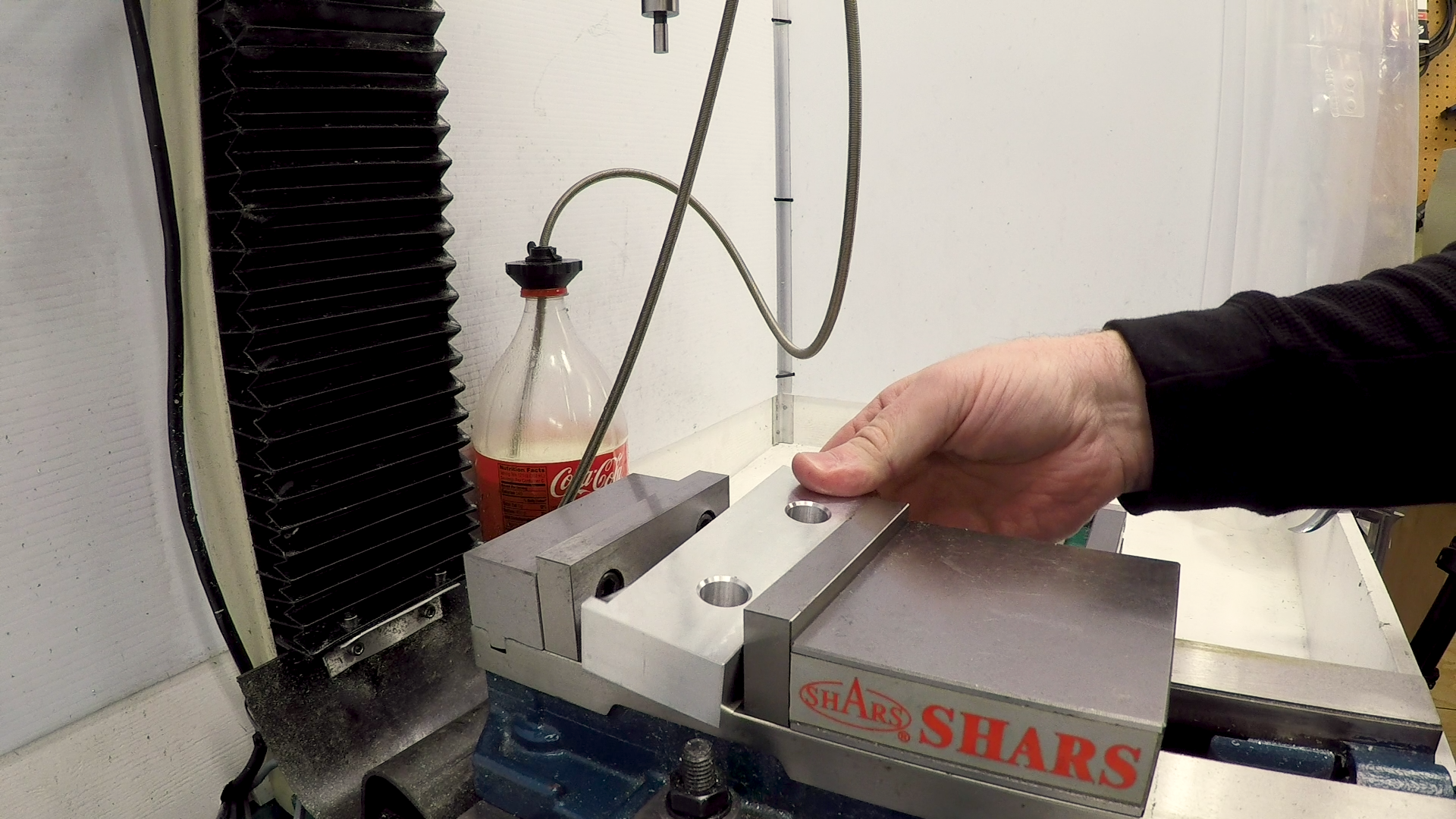
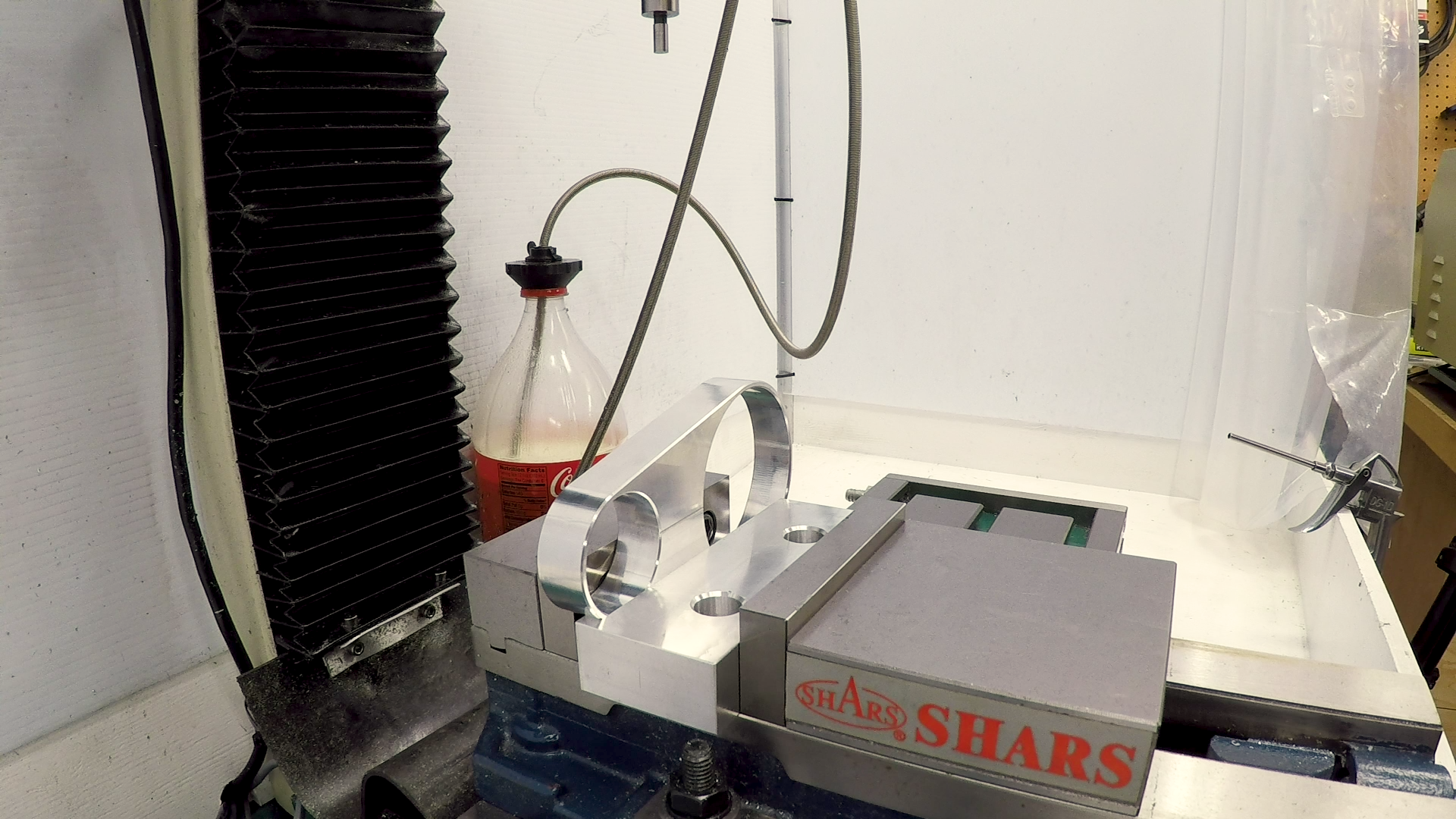
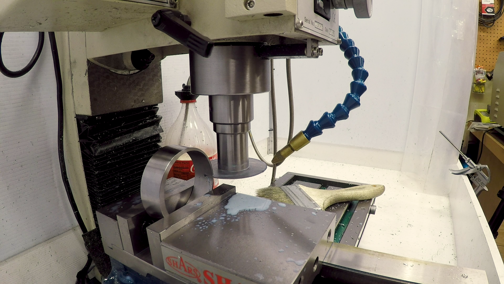
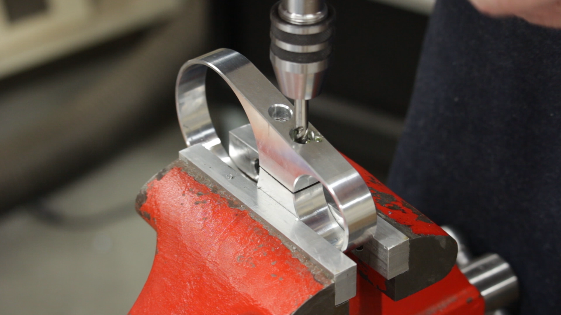
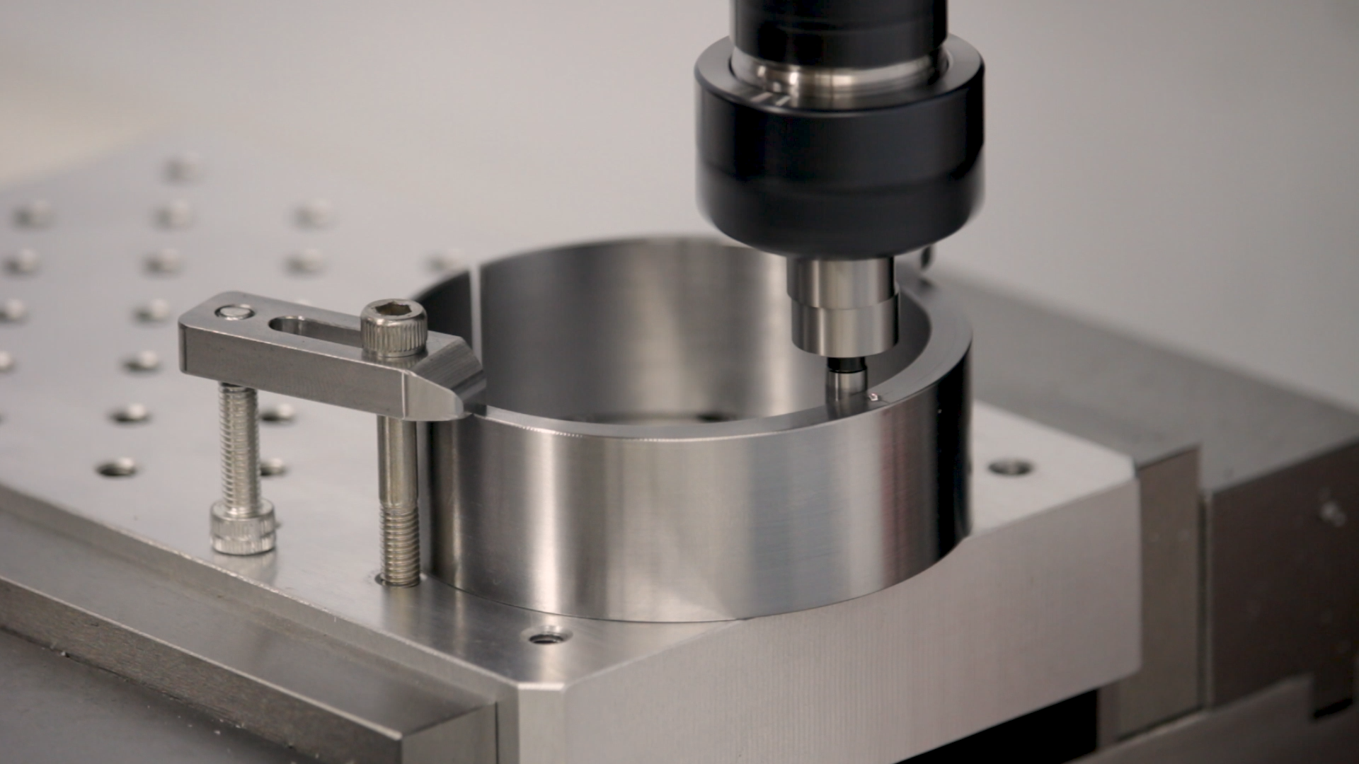
Before I could drill the holes, I had to figure out how to set up the part at the right angle. I engraved a line on the part that I had intended to use for this setup. But as I was thinking about it, I realized that I still have the left-over soft jaws that are already machined to the shape of the part. I laid one of these down in the vise and the part fit into it, perfectly level, and ready to drill.
The Countersinks
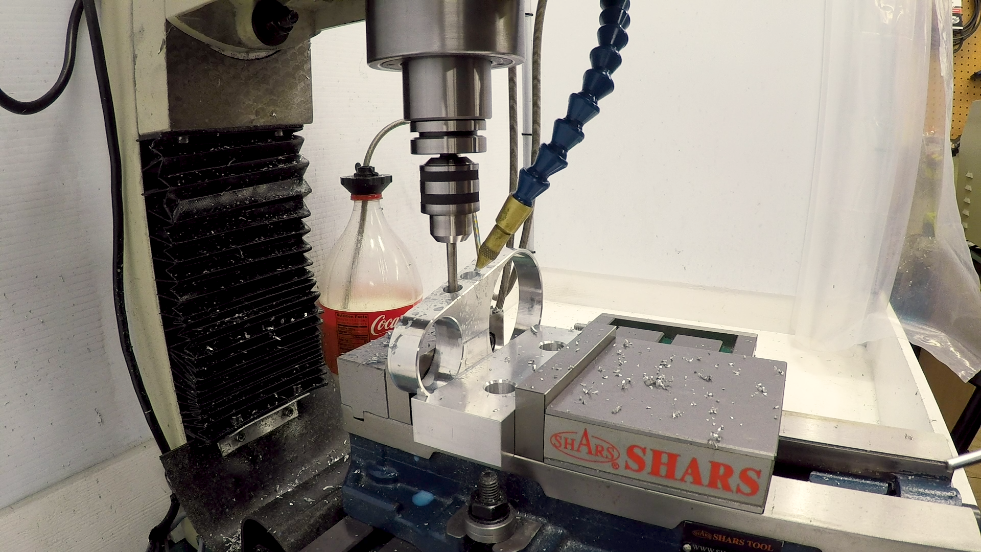
Starting a drill on an angled surface is possible, but not easy. I decided instead to cut the countersinks first, so I would have the flat bottom of the countersink to start the drill. I interpolated the countersink holes using a 1/4″ 3-flute end mill. I took it very slowly because it’s sometimes hard to clear chips from a small hole like this and ramping into the cut can tend to chatter.
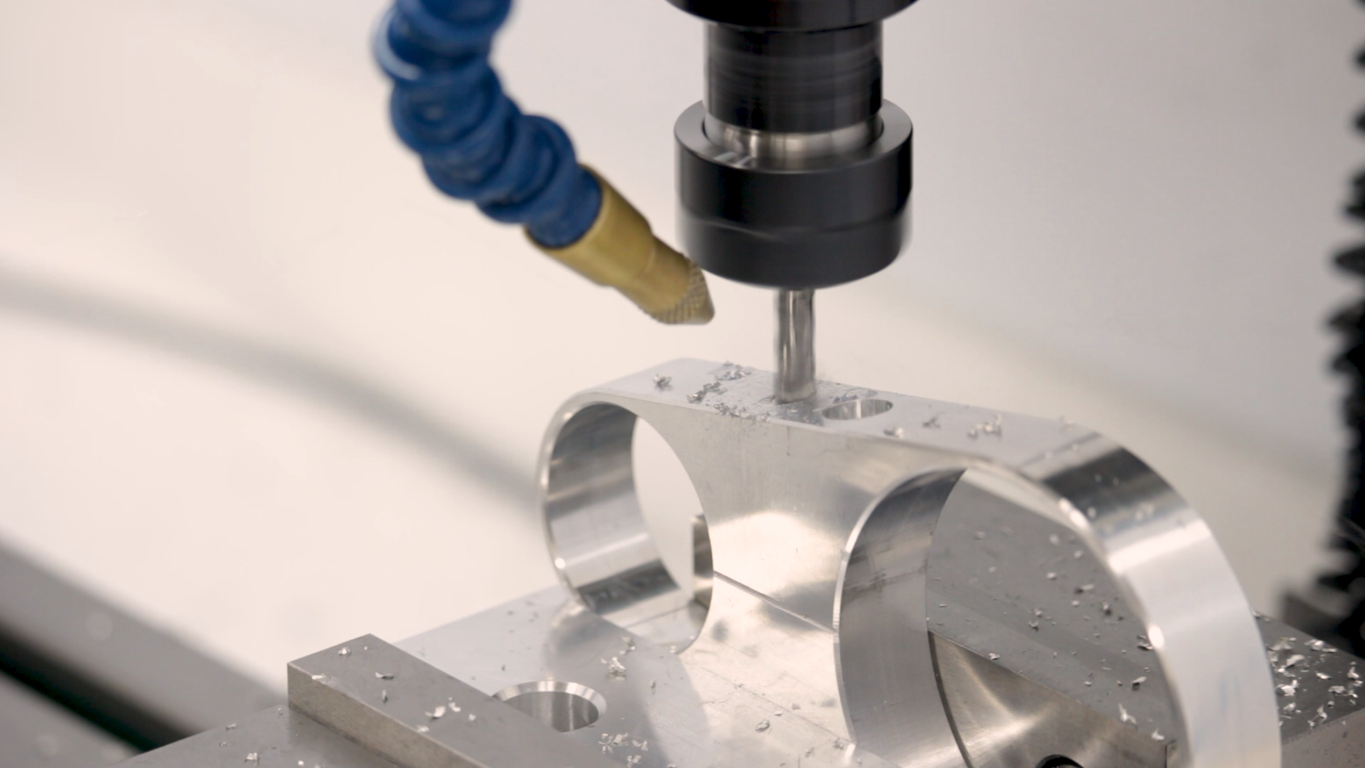
As it turned out, the countersinks cut very easily.
Drilling
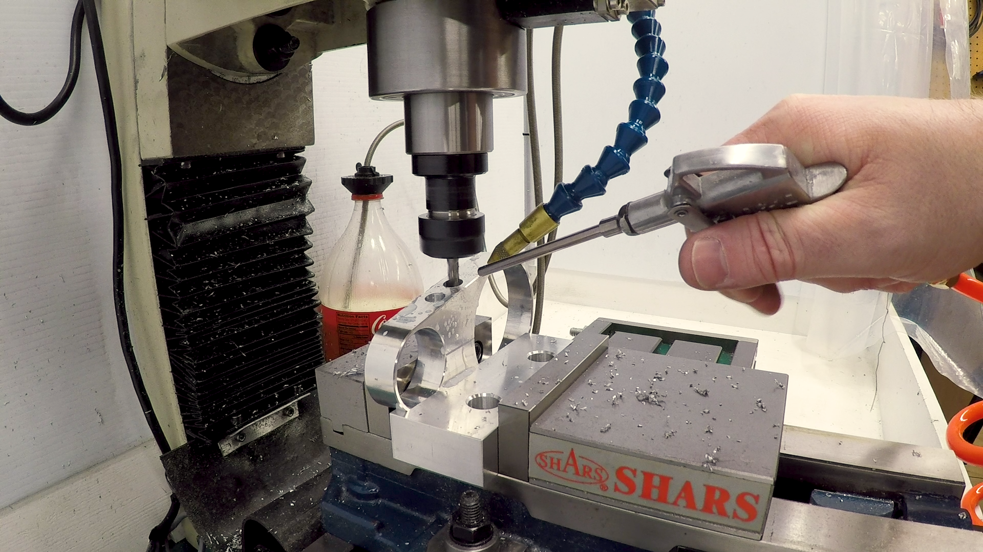
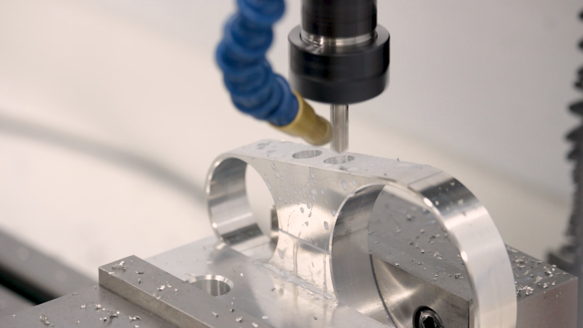
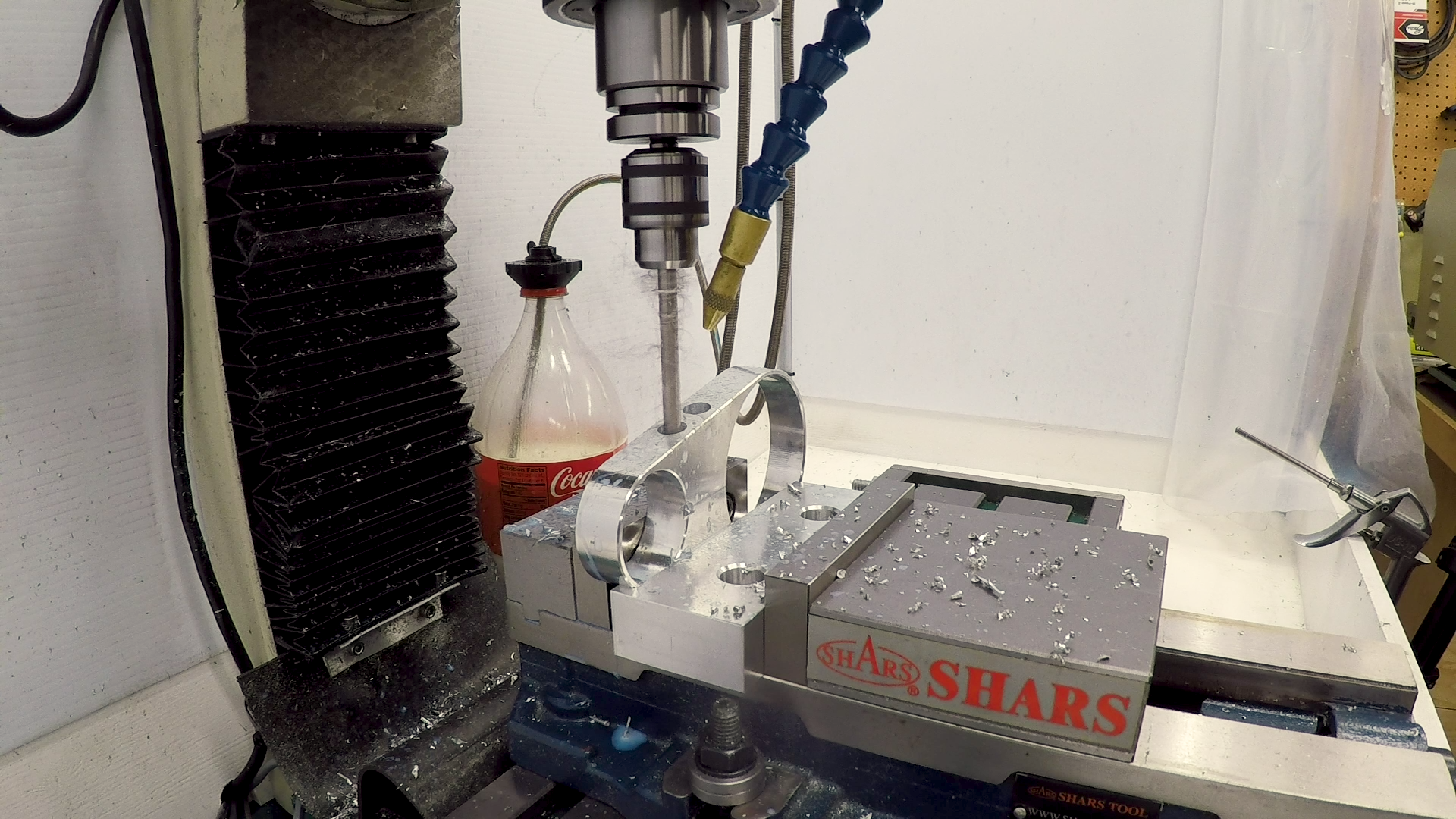
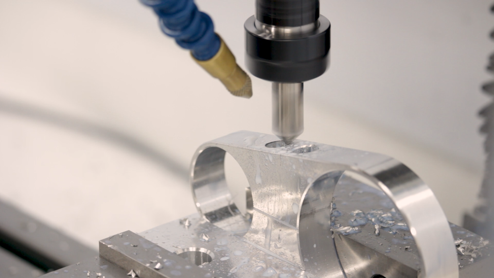
Now that I had the flat-bottomed countersinks, it was a simple matter of spotting the holes with at 120-degree spotting drill and then drilling to full depth with the tap size and opening up the hole with a clearance drill. The clearance hole extends about halfway down–exactly to the split line in the clamp. This way, the screw is free in the top half and threaded in the bottom.
3D Chamfers
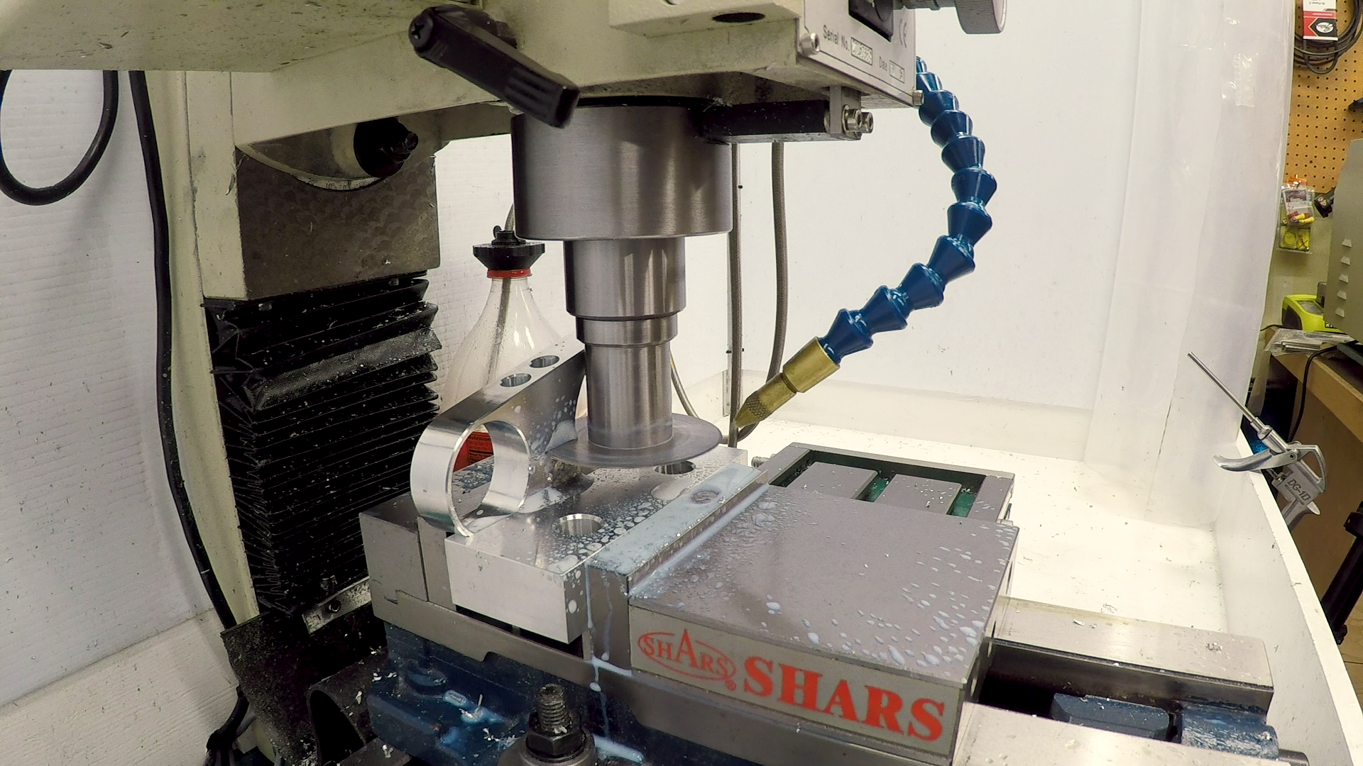
I chanferred the tops of the countersink holes for appearance. This is actually tougher than it looks because the top of the hole is angled. And you can’t rotate the countersink to enter at that angle, because the surface of the edge isn’t actually round–it’s elongated due to the angle.
The solution is a 3D chamfer. In Fusion 360, this is accomplished with an offset trace operation. I used the trusty YG-1 1/2″ 90-degree spotting drill again. This is my go-to chamfering tool.
Slitting
To split the clamp, I used a 2-3/4″ .040″ slitting saw in a shop-made TTS-style arbor. I measured the tool length in advance, so I was able to just dial it right to the correct height and make the slit in one pass. There was no drama, and the split ended up exactly on the mark. The .040″ slit left no trace at all of the .040″ engraving line left from the previous machining.
While I had the slitting saw in the machine, I went ahead and split the eccentric.
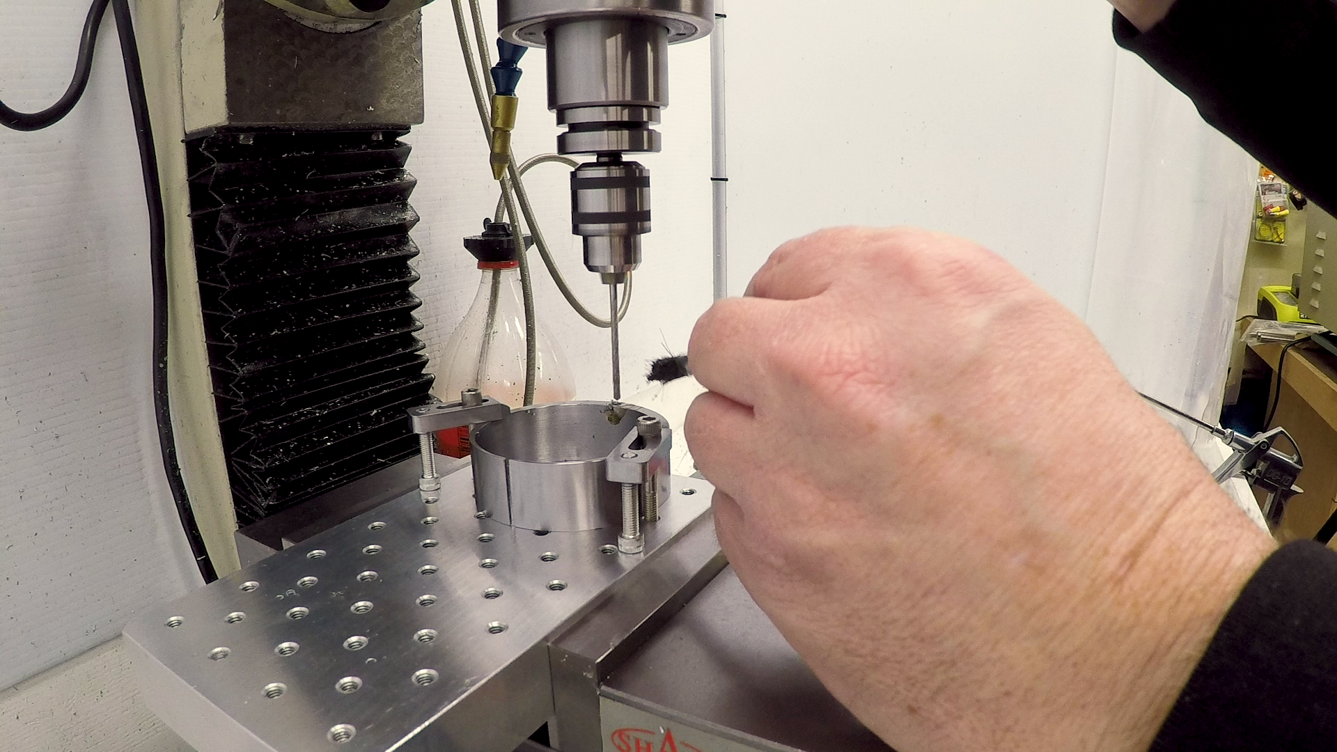
Tapping and Fitting
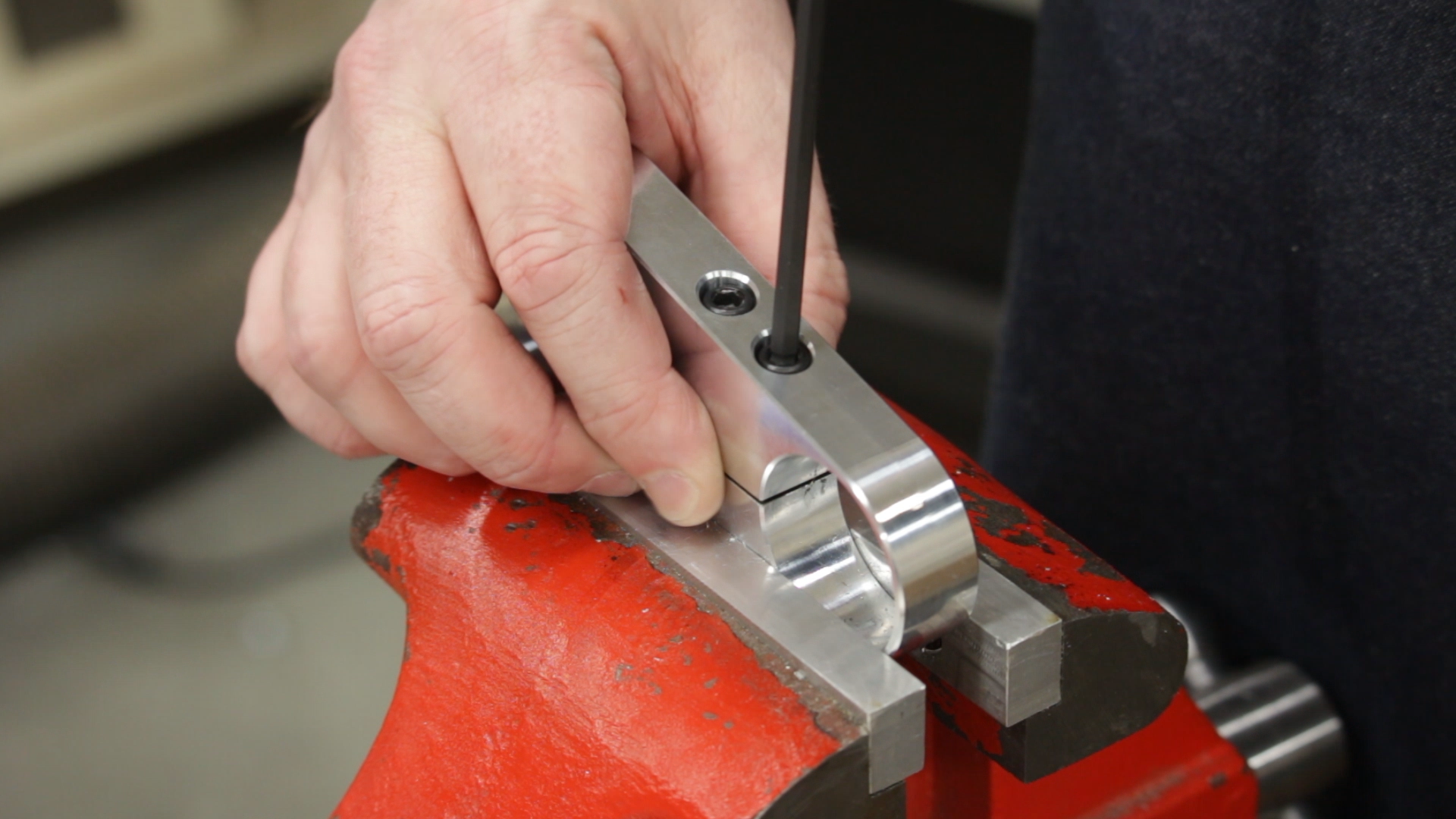
I tapped the clamping holes at the bench vise. It was an easy task because the clamp already has a deep clearance hole that made a perfect tap guide.
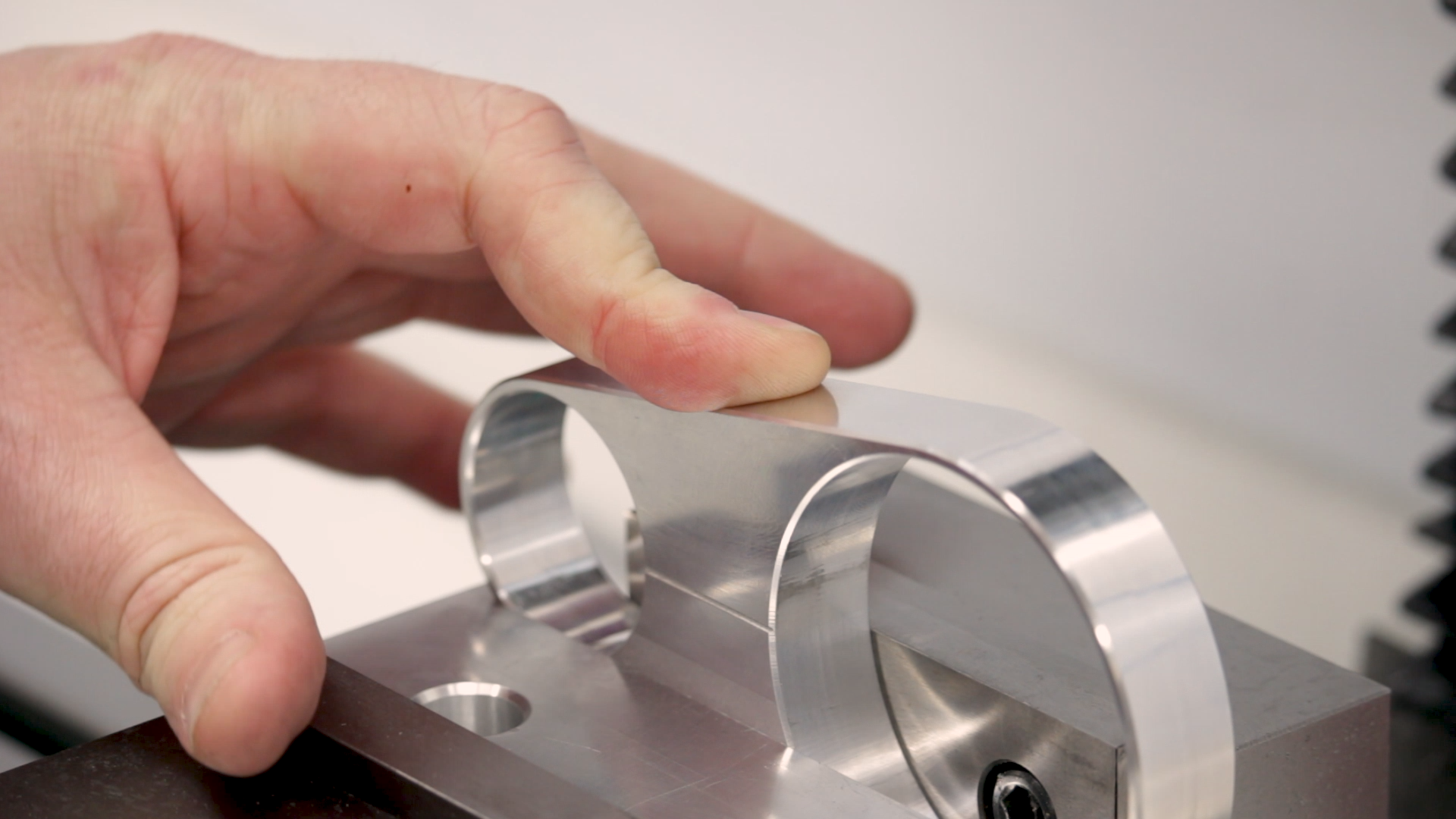
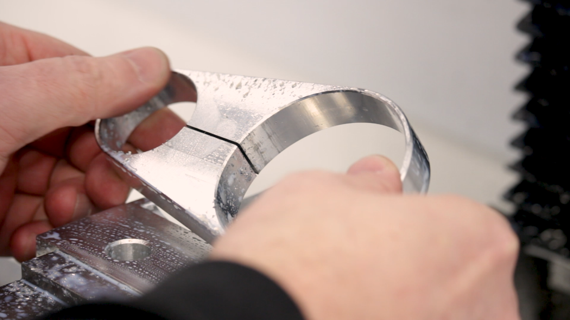
The screws of course fit perfectly, and I was surprised how compliant the aluminum clamp was. I had feared it would be difficult to clamp, but the aluminum turned out to be thin enough to completely compress with hand pressure. The grip on the spindle and motor are more than sufficient. Even the steel eccentric clamped down on the not-so-round motor very easily.
Drilling the Eccentric
As it turned out, it was pretty difficult to rotate the eccentric to adjust the motor. I took it back to the mill and drilled and reamed a hole for a 1/8″ pin to make this job easier. At some point, I’ll make a proper face or hook spanner for this task.

Up Next
That’s the motor clamp complete. The motor and spindle clamp securely and there’s plenty of adjustment range to mount and tighten the belt.

Next time, we’ll start on the toolpost clamp.
If you’re following along with the build, here are some links to some of the tools used in the video:
*This site contains affiliate links for which I may be compensated
- YG-1 1/4″ Alu-Power end mill (eBay*): https://goo.gl/GpBkLh
- YG-1 1/2″ 90 degree spotting drill (eBay*): https://goo.gl/CpoZ31
- General Tools Tap Wrench Set (Amazon*): http://amzn.to/2znrcOW
- Allen SAE Metric Hex Key Set (*Amazon): http://amzn.to/2BsnIfP
- HFS 190-Piece (0.061-0.250″) Gage Pin Set Minus (Amazon*): http://amzn.to/2DDSAf3
- Noga Deburring Set (Amazon*): http://amzn.to/2xMfiPz
- Grizzly V-Block Set (*Amazon): http://amzn.to/2BVj7DX