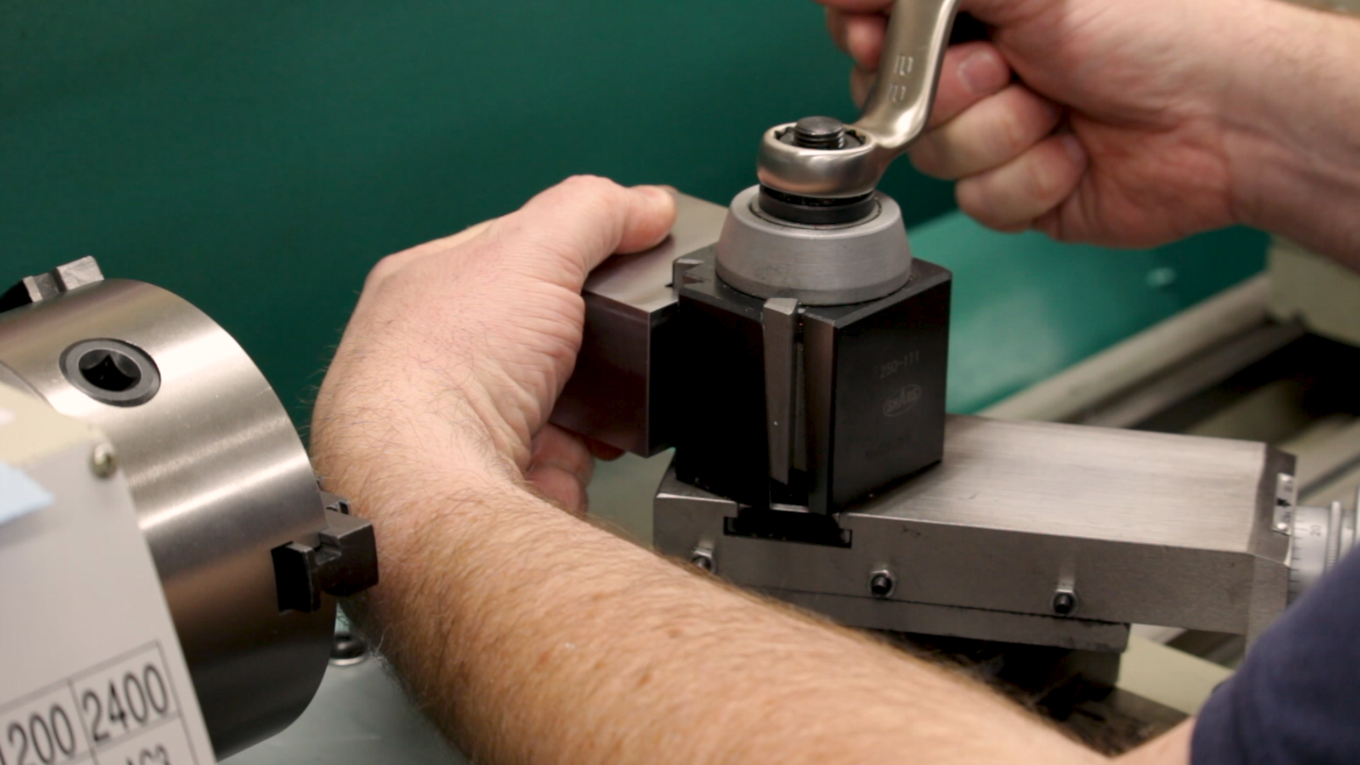
Today, we’re starting on the toolpost clamp for the grinder. This is the part that mounts the spindle of the grinder to the AXA toolpost in the lathe.
The Stock
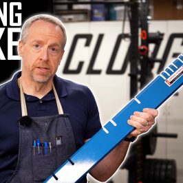
The toolpost clamp is made out of mild steel. I started with an ugly offcut from my metal supplier. After chopping off most of the excess with the band saw, I squared up the part and faced it to size on all six sides with a carbide face mill. That 2-1/2″ face mill that I have is really too much for my little mill–at least in steel. The mill groaned, complained and hammered away, and in the end the part came out looking great.
Just check out that surface finish! To get it, I had to push the mill hard. Really hard. Way too hard. I was running the 2-1/2″ cutter at 2200RPM, 20 IPM, .020″ DOC. That’s about one cubic inch per minute of material removal, which is fantastic, but as I said, the poor little mill would barely take it.
The chips were coming off between dark blue and black, but it’s hard to argue with the finish.
Measuring Dovetails
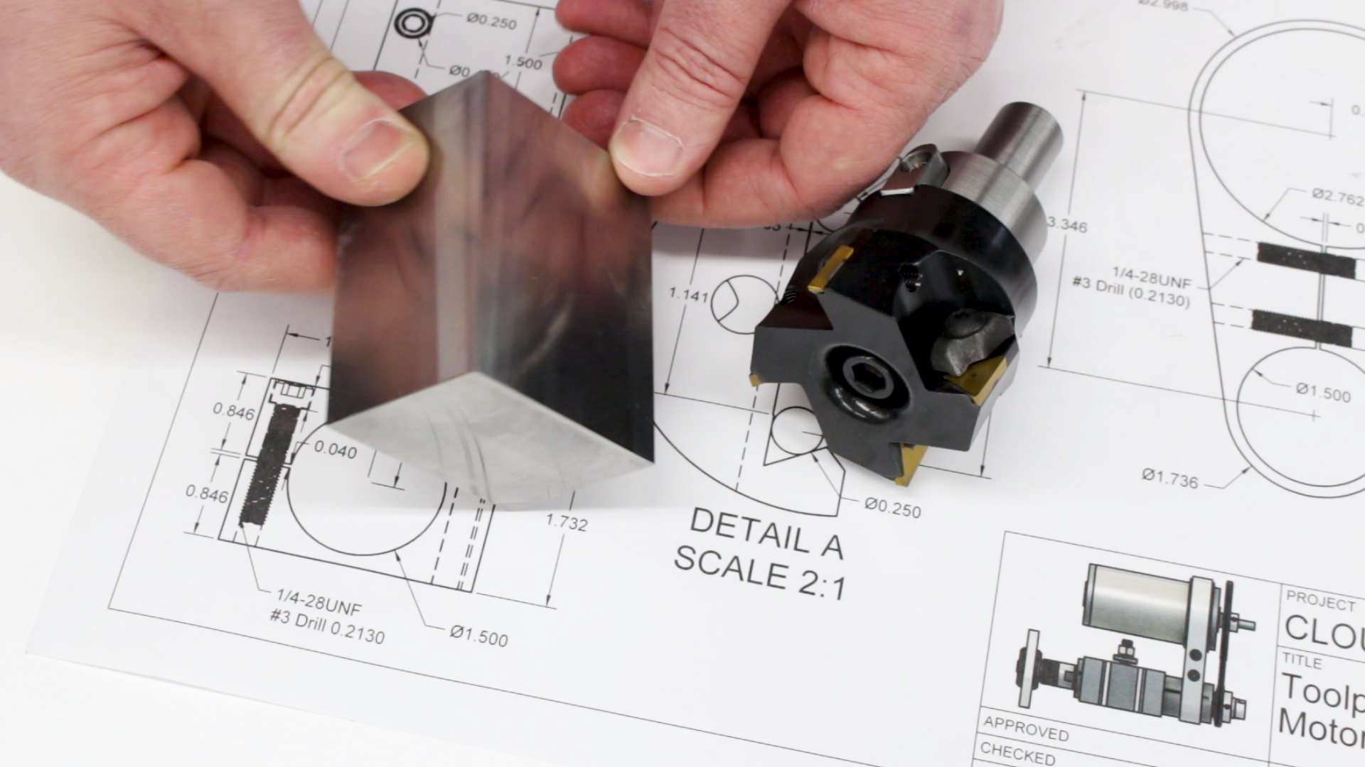
I started by measuring one of the dovetails on an existing toolholder. This is usually done with a pair of pins. I didn’t have two pins the same size, so I used one .250″ pin and one .249″ frome my gauge pin set and adjusted the drawings in Fusion 360 to gauge with these pins. I measured the gap with gauge blocks to be 1.008″. This was my target.
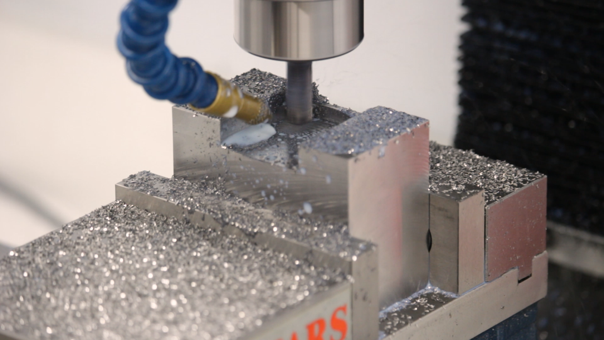
Roughing the Dovetail
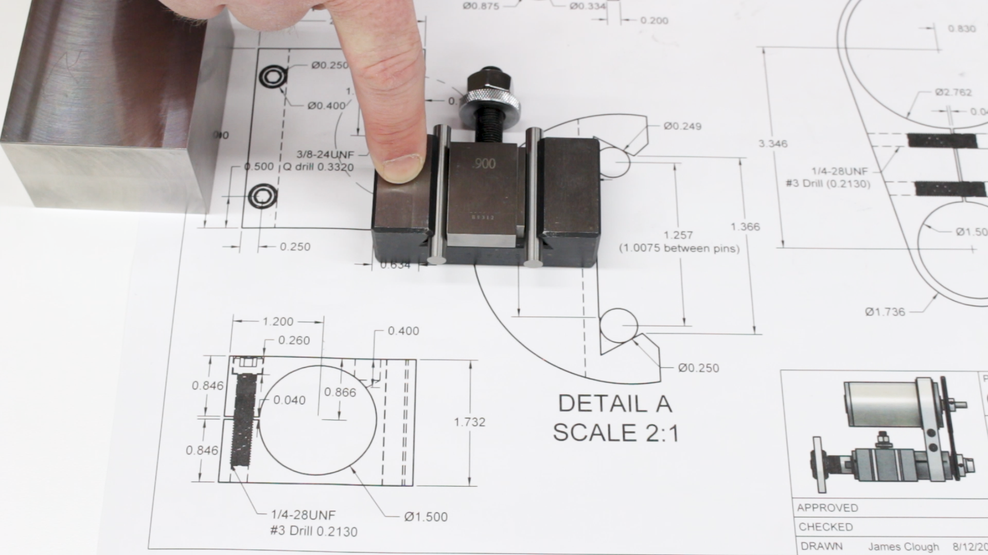
I roughed out the majority of the material with a 3/8″ fine-pitch roughing end mill. This one was a YG-1 Tank-Power. Funny name aside, it’s an amazing little tool. It plows a lot of steel out of the way in a short time and the little Grizzly mill seems to like it just fine. This is one tool, though, that I don’t run in an ER collet holder.
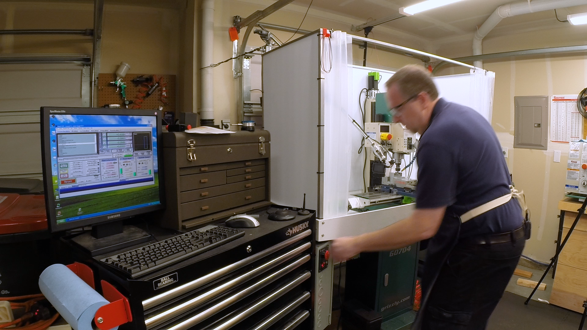
I run most of my CNC tools in TTS-style collet holders. This allows me to pre-measure the tool lengths and set them up in the tool table in MACH3 so I can swap tools without re-zeroing the Z axis. This is great, but it comes at the expense of rigidity. When roughing steel, I wand the setup to be as rigid as possible, so I always set the tool up directly in an R8 collet in the spindle.
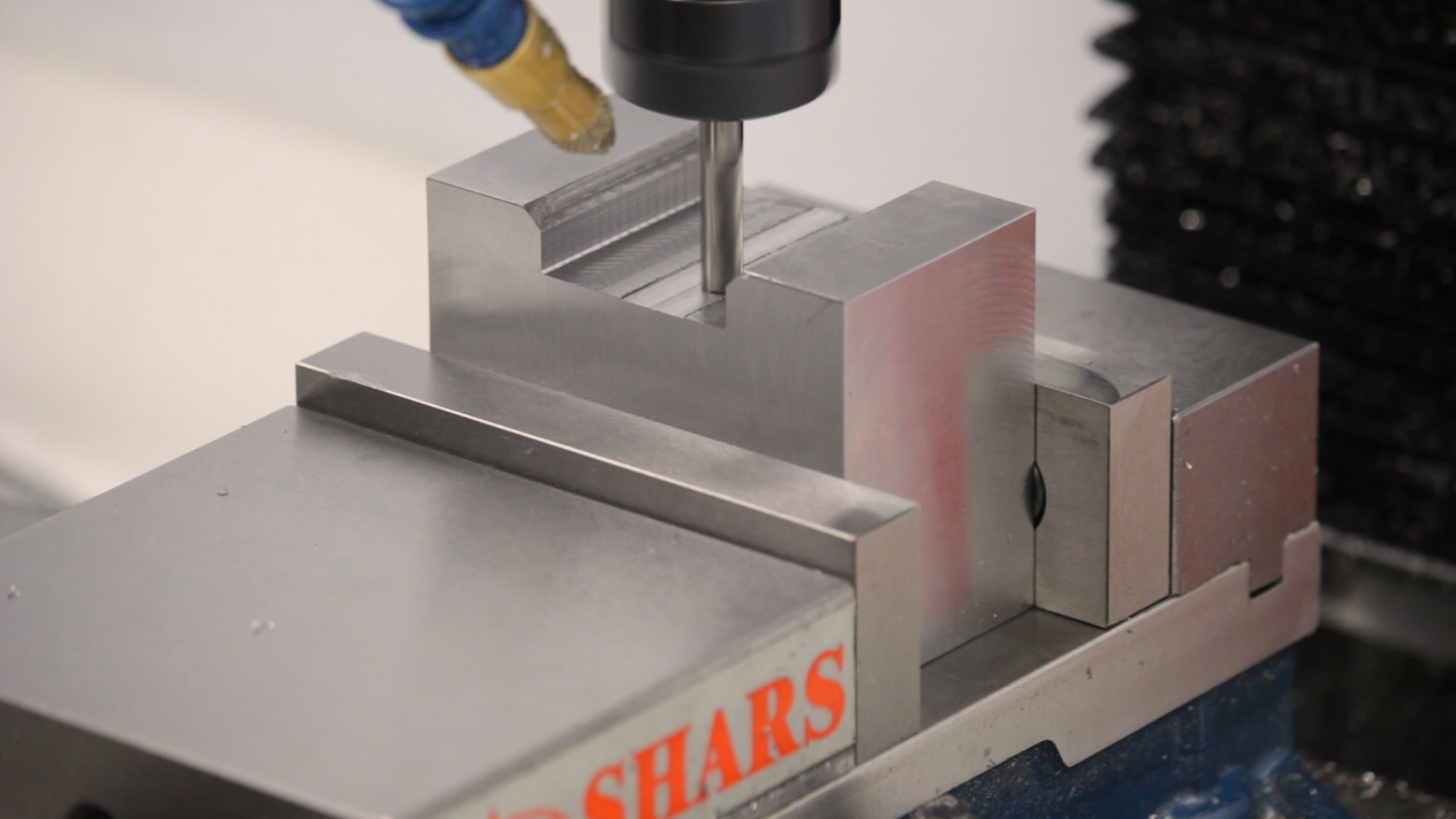
Relief Facets
My dovetail cutter won’t take the entire .385″ depth of the dovetail because the cutting flutes aren’t that long. To make it work, I took a cue from some of the other toolholders I have and cut relief facets on the sides first. To do this, I set the block up at 45 degrees in the vise using an angle block and zeroed on the top corner with the edge finding tool we made in a previous video.
A 1/4″ carbide end mill made short work of the facets.


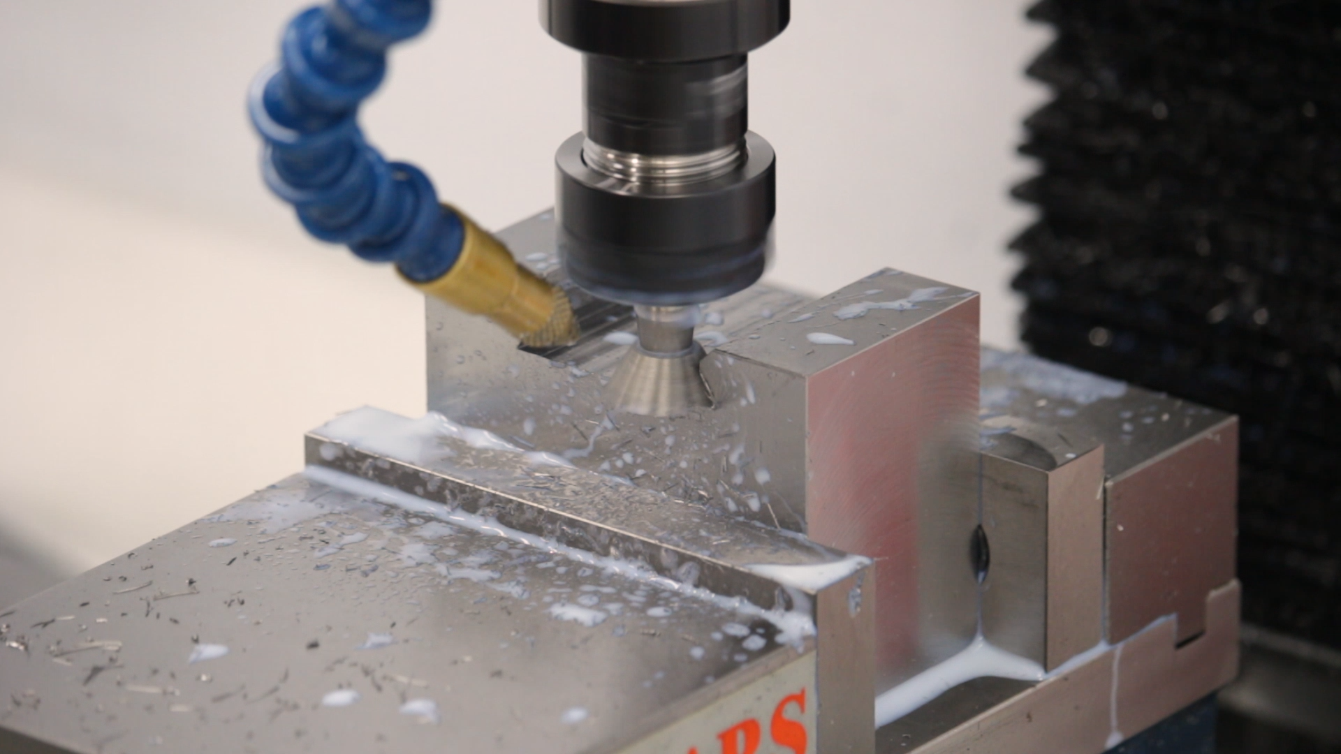
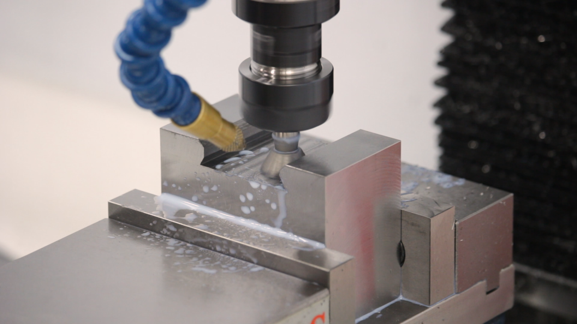
Finishing the Dovetail
The same 1/4″ end mill smoothed out the bottom of the slot and finished the edges to size.
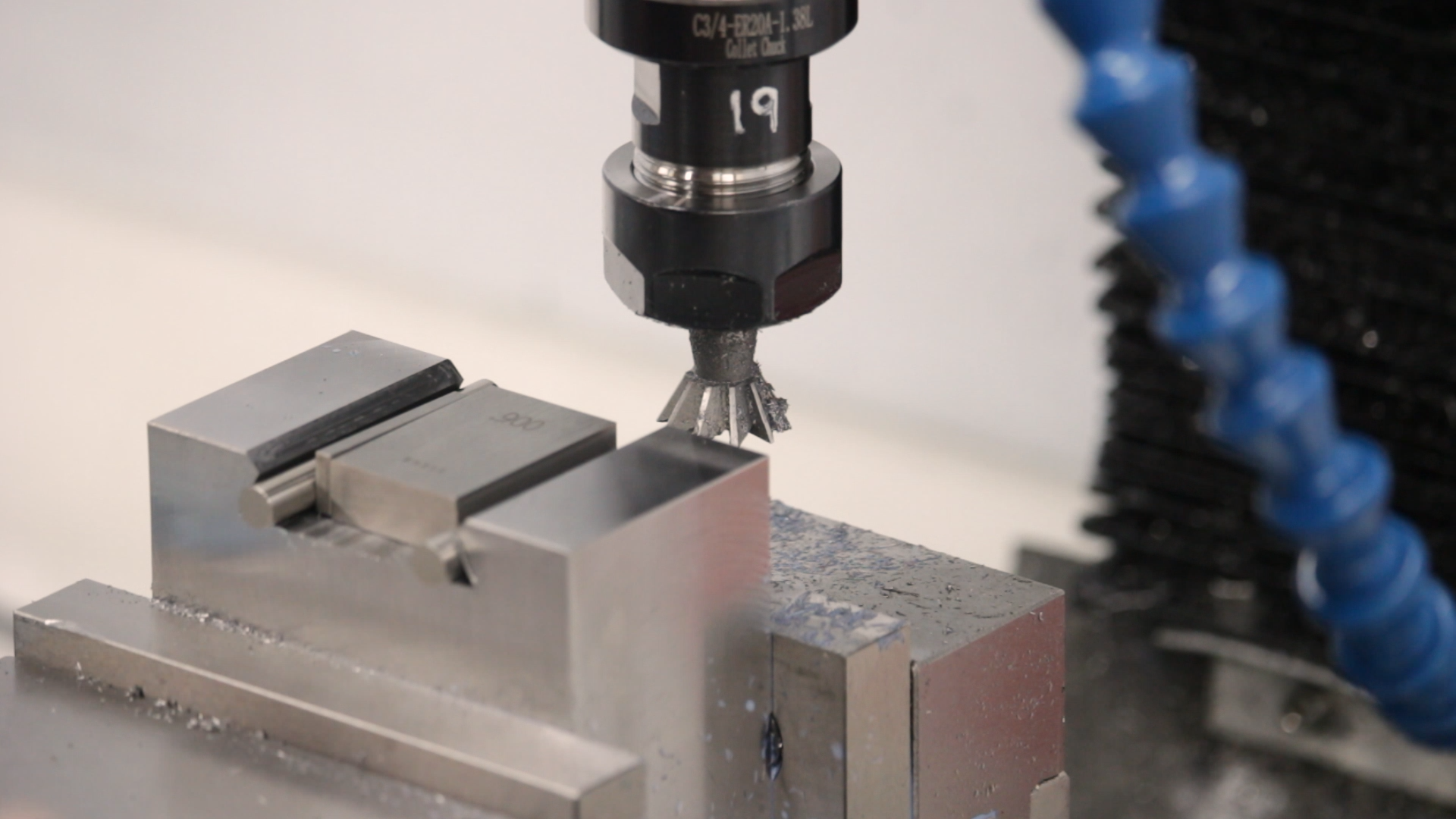
Next came the dovetail cutter itself. I was foolishly optimistic when setting up the CAM to cut the actual dovetail. I figured with a 10-tooth cutter running nice and slow (300RPM) it should be easy to take .001″ per tooth, in .050″ passes. This turned out to be completely wrong. The first pass went fine, but the second pass started pounding and catching and finally stopped the spindle cold, sending me diving for the E-stop switch.

What went wrong?
Looking at the video more carefully, it seems pretty clear that the dovetail cutter I have isn’t ground very evenly. The teeth are not all the same, which means the chipload is not spread evenly. Maybe these things are like slitting saws and woodruff cutters in that a few of the teeth end up doing most of the work. In any case, it was clear I was taking way too much material in one pass.
After resetting the mill and checking the tram, I finished the dovetail, driving the machine by hand, making .010″ and finally .005″ passes to finish out the dovetail to size.
Up Next
The dovetail came out within about .0005″ of the target size, but I ended up taking a little bit more to ease the fit on the toolpost. It fit on the post, but it was clumsy to get on and off. An extra .0005″ per side made it slide on easily and it still locks in place well.
Next time, we’ll poke a hole through the block to accept the spindle.
If you’re following along with the build, here are some links to some of the tools used in the video:
*This site contains affiliate links for which I may be compensated
- 2.5″ Carbide Face Mill (Amazon*): http://amzn.to/2Bo1VXk
- HFS 190-Piece (0.061-0.250″) Gage Pin Set Minus (Amazon*): http://amzn.to/2DDSAf3
- Shars 81 piece gauge block set (eBay*): https://goo.gl/DGtbHE
- YG-1 Tank-Power 3/8″ powdered metal roughing end mill (eBay*): https://goo.gl/4QmiZi
- YG-1 4-Flute Carbide 1/4″ end mill (eBay*): https://goo.gl/1dLomn