Which Extruder Are You Building?
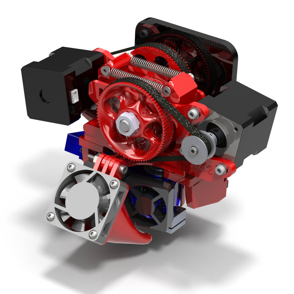
These instructions are for the Itty Bitty Double FLEX V2 extruder. The original (V1) Itty Bitty Double Flex extruder parts look a little different, but is uses the same instructions. If you’re looking for the original Itty Bitty Double Extruder, you should start here:
Itty Bitty Double Extruder
Before You Begin
 Make sure you have everything you need:
- Printed parts (for your chosen hot ends):
- Extruder block (3mm or 1.75mm)
- Idler blocks (2)
- Idler pins (2)
- 2mm spacers (2)
- 1mm spacers (2)
- 80-tooth GT2 Pulleys (2)
- Double groove mount
- X carriage shelf
- X carriage support bracket (right side)
- X carriage servo support bracket (left side)
- Z probe arm
- Hot end cooling shroud
- Print cooling fan shroud
- Hardware kit: Itty Bitty Double Extruder Hardware Kit
- Hobbed bolts with jam nuts (2): Hobbed Extruder Bolt
- Hot ends
- RRD Hexagon Hot ends (2) for 3mm or 1,75mm filament (NOTE: V2 supports Hexagon AO)
- E3Dv6 Hot ends (2) for 3mm or 1.75mm filament
- NEMA 14 stepper motors (2) NEMA 14 Stepper Motor
- 25x15x10mm fan (Hexagon hot ends only)
- 40x40x10mm fan
- HXT900 Servo: HXT900 Servo
- Z probe snap switch
- recommended: Digi-Key
- You can also use the snap switch that came with your MakerFarm printer
- Tools
- Hex (Allen) wrenches: 2mm, 2.5mm
- Needle-nose pliers
- Scissors
- (Optional) Taps: M3x0.5, M2.5×0.45
Printable Files
Download the printable files here:
Itty Bitty Double FLEX Extruder Printable Parts
All of the files are included for the entire extruder system for 1.75mm and 3mm filament, Hexagon and E3Dv6 hot ends. To assemble the entire system you will need to print:
One extruder block:
- For 3mm hot ends: Double Flex Block-300Universal.STL
- For 1.75mm hot ends without a liner: Double Flex Block-175Universal.STL
- For 1.75mm E3D hot ends with a PTFE liner and fitting: Double Flex Block-175E3dLiner.STL
Hot end-specific parts:
- Hexagon hot ends: All of the parts in the “Hexagon Specific” folder
- E3D hot ends: All of the parts in the “e3dv6 Specific” folder
Common parts:
- All of the parts in the “Common Parts” folder
Assembly Instructions
Select the type of hot end you are using:
Select your hot end type to see detailed assembly instructions.
Printed Part Cleanup
 |
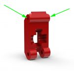
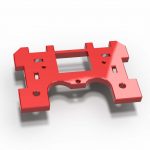
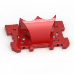
- Remove support material from the filament channels in the main extruder block.
|
 |
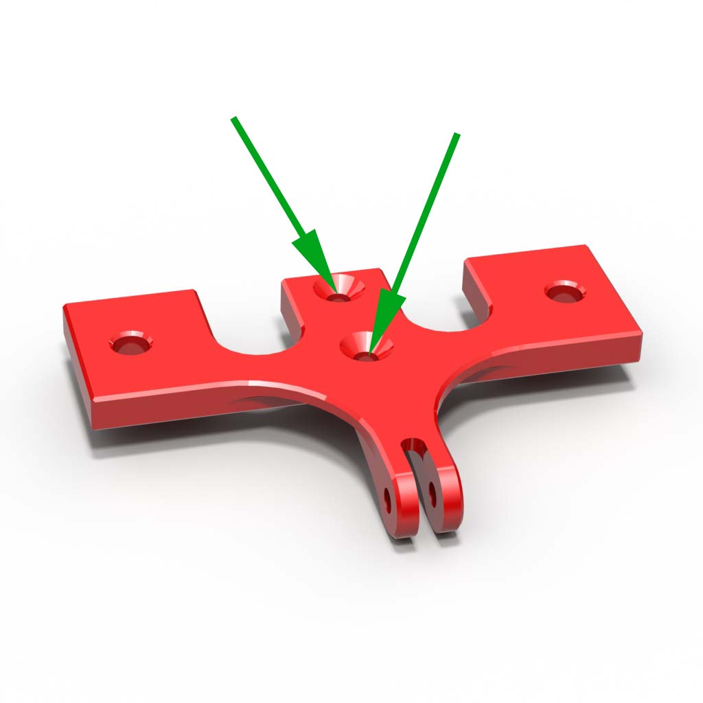
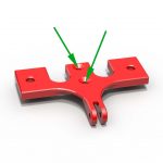
- Clean out the countersink holes in the bottom of the X carriage shelf. Make sure M3 flat-head screws will fit flush with the surface.
|
 |
- (Optional) Tap two holes in the X carriage shelf with M3x0.5 threads. If you don’t have an M3 tap, you may be able to form threads in the part by forcing in an M3 screw. You may need to drill the holes out first, depending on your printer.
|
 |
- (Optional) Tap two holes in each idler block with M3x0.5 threads. If you don’t have an M3 tap, you may be able to form threads in the part by forcing in an M3 screw. You may need to drill the holes out first, depending on your printer. Be careful not to split the part, as the holes are parallel to the layers.
|
 |
-
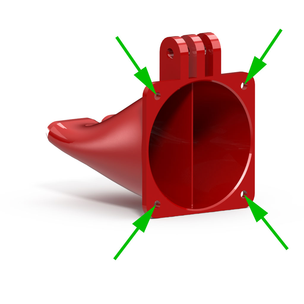
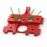
- (Optional) Tap four holes in the cooling fan shroud with M3x0.5 threads. If you don’t have an M3 tap, you may be able to form threads in the part by forcing in an M3 screw. You may need to drill the holes out first, depending on your printer.
|
 |
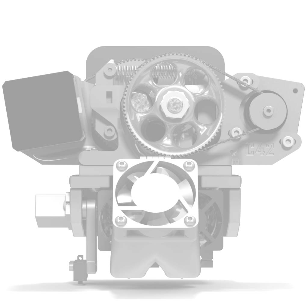
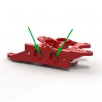
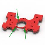
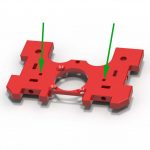
- Clean out the two countersink holes in the bottom of the double groove mount. Make sure M3 flat-head screws will fit flush with the surface.
|
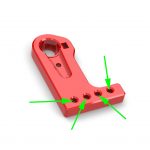 |
- (Optional) Tap four holes in the Z probe arm with M2.5×0.45 threads. Your switch will only use two of the four holes. If you don’t have an M2.5 tap, you may be able to form threads in the part by forcing in an M2.5 screw. You may need to drill the holes out first, depending on your printer.
|
 |
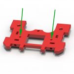
- Make sure the groove mount fits around the blocks on the X carriage shelf. If it does not, remove plastic in the marked areas to make it fit.
|
Idler Blocks
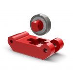 |
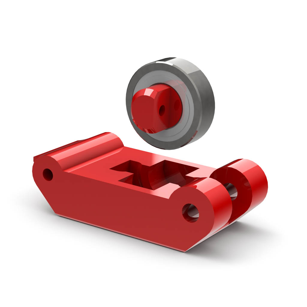
- Insert an idler pin into a 688ZZ bearing and insert it into one of the idler blocks. You may need to round sharp edges on the pin, depending on how well your printer controls the first layer. Sand the pin, if needed, to make it fit easily into the bearing.
|
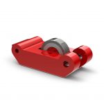 |
- Insert a sharp tool into one of the holes in the idler pin and rotate it to lock it into place. A scratch awl works well for this.
- Repeat for the other pin and idler block.
|
 |
- Install two M3x12 flat head screws. These are the anchor points for the extension springs.
|
Extruder Block
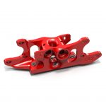 |
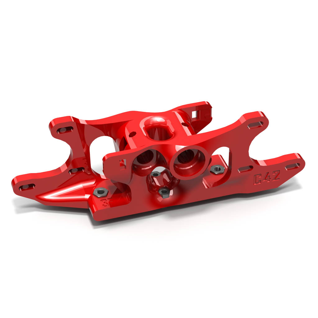
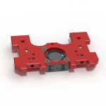
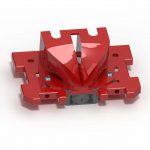
- Press two M4 nuts and two M3 nuts into the base of the extruder block. These will serve as anchors for the mounting and groove mount tensioning screws.
|
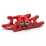 |
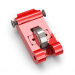
- Press four 688ZZ bearings into the extruder block. You may need to clean out the bearing seats, depending how well your printer prints overhangs.
|
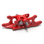 |
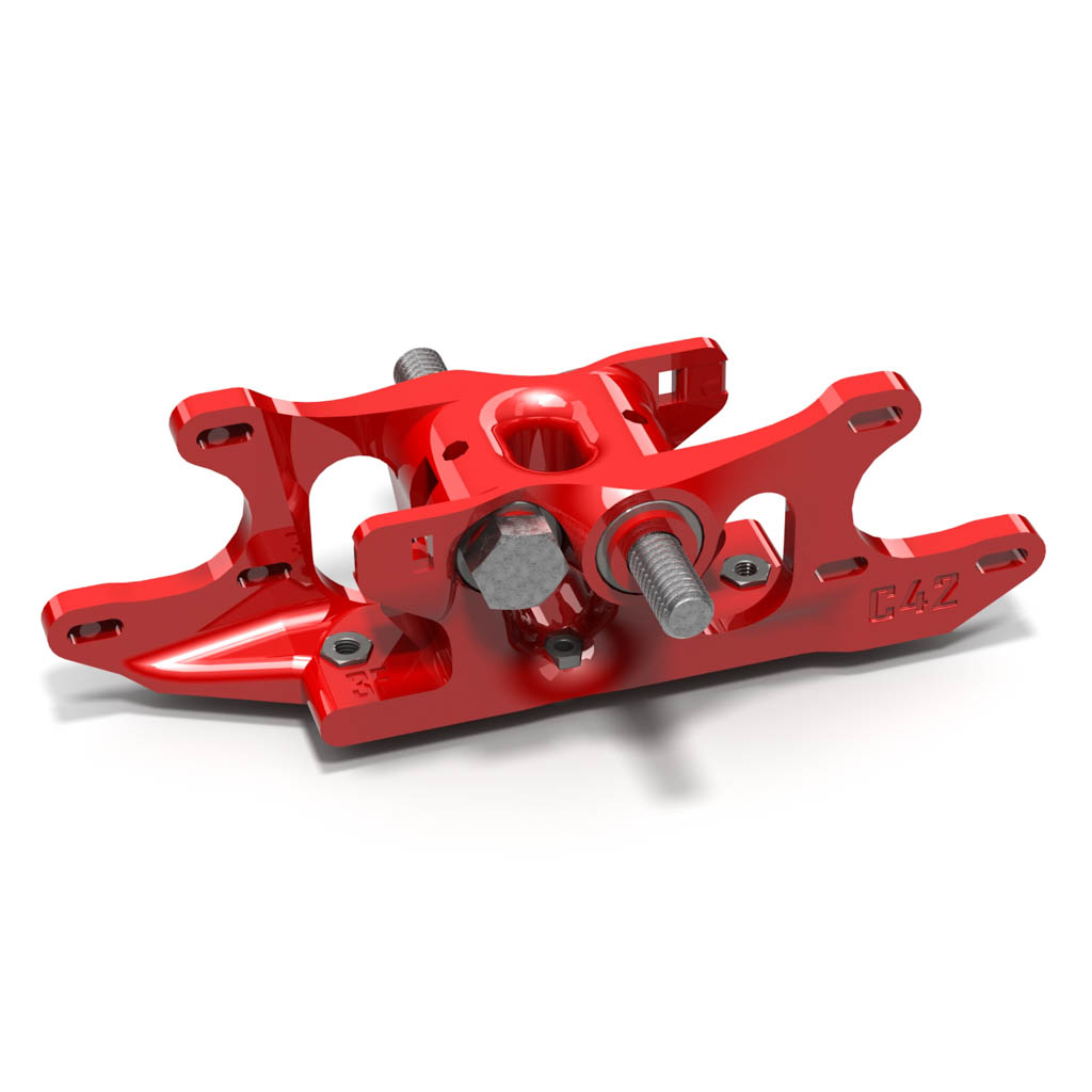
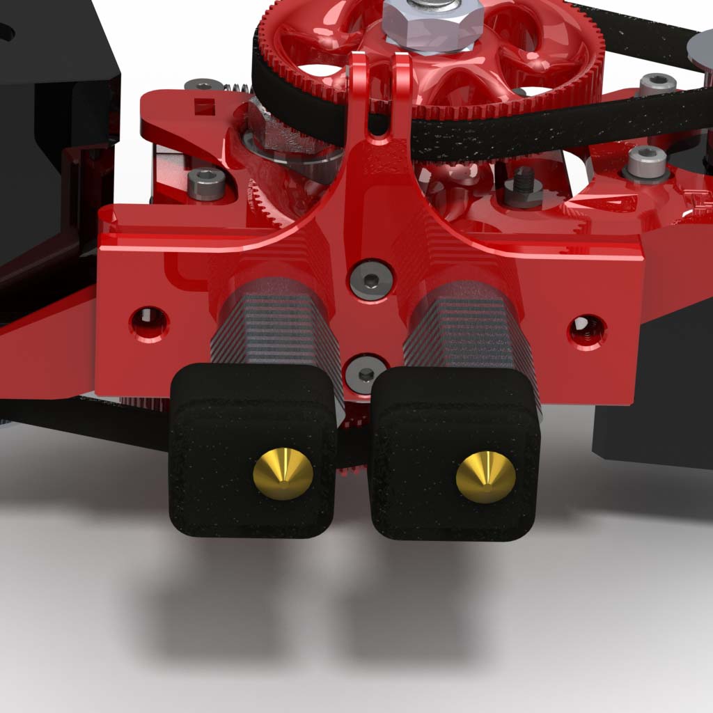
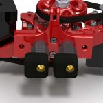
- Install a 1mm spacer onto each hobbed bolt. The beveled side goes toward the bolt head.
- Install the hobbed bolts into the extruder block.
- Install a 2mm spacer on the threaded end of each bolt after it is inserted.
|
 |
- Press one of the jam nuts that came with each hobbed bolt into each pulley.
- Install the pulleys on the hobbed bolts.
- Adjust each pulley so the bolt turns freely but has no end play and lock it in place with a jam nut.
|
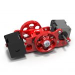 |
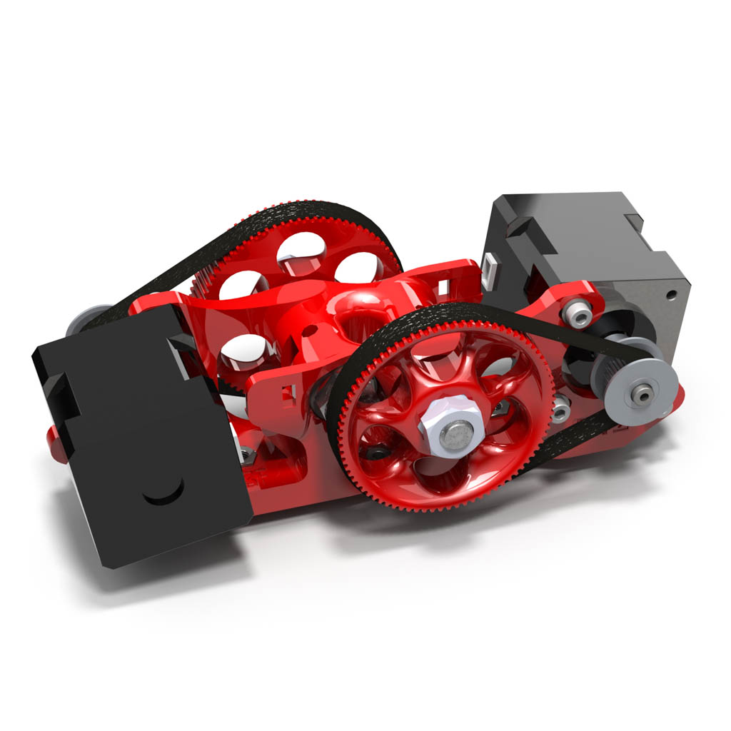
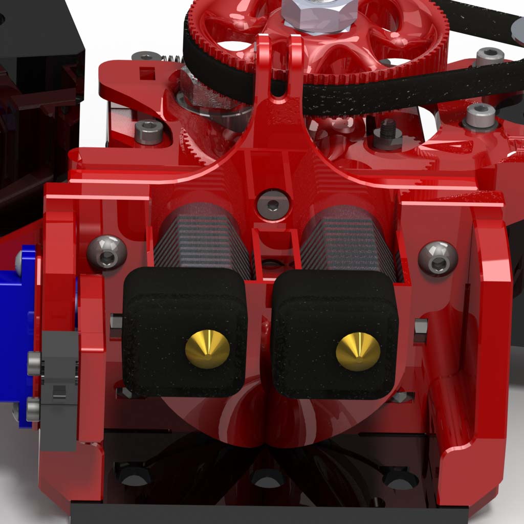
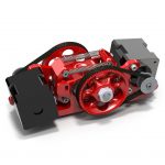
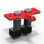
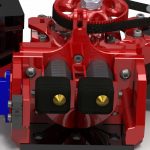
- Install the motors with six M3x8 screws and six M3 washers. Leave the screws loose for now.
|
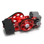 |
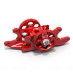
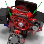
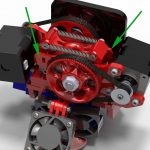
- Install a 20-tooth pulley on each motor.
- Slip a belt over the small pulley first, side the motor up and slip it onto the large pulley; repeat for the other side.
- Adjust the belt tension by moving the motor and tighten the motor screws. The belt does not stretch, so it doesn’t need to be taut. Just take out the slack.
|
 |
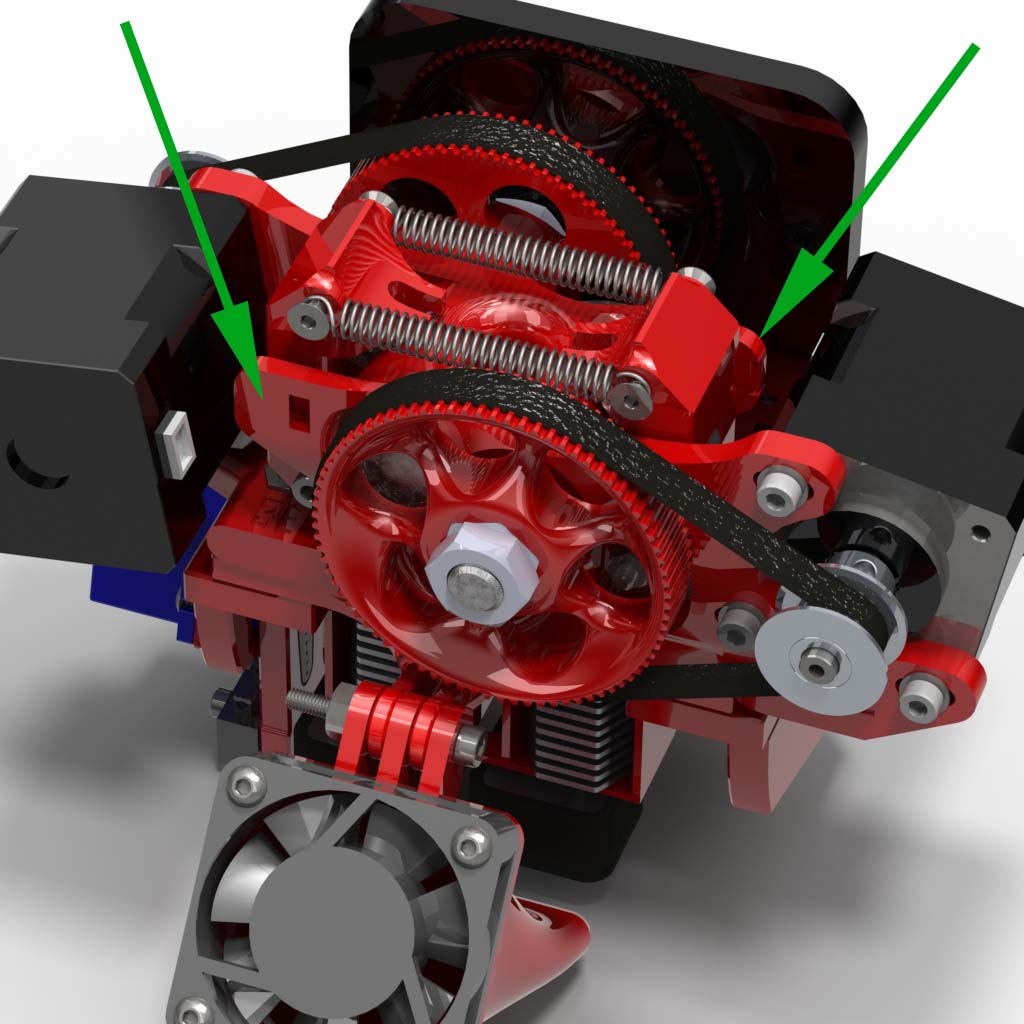
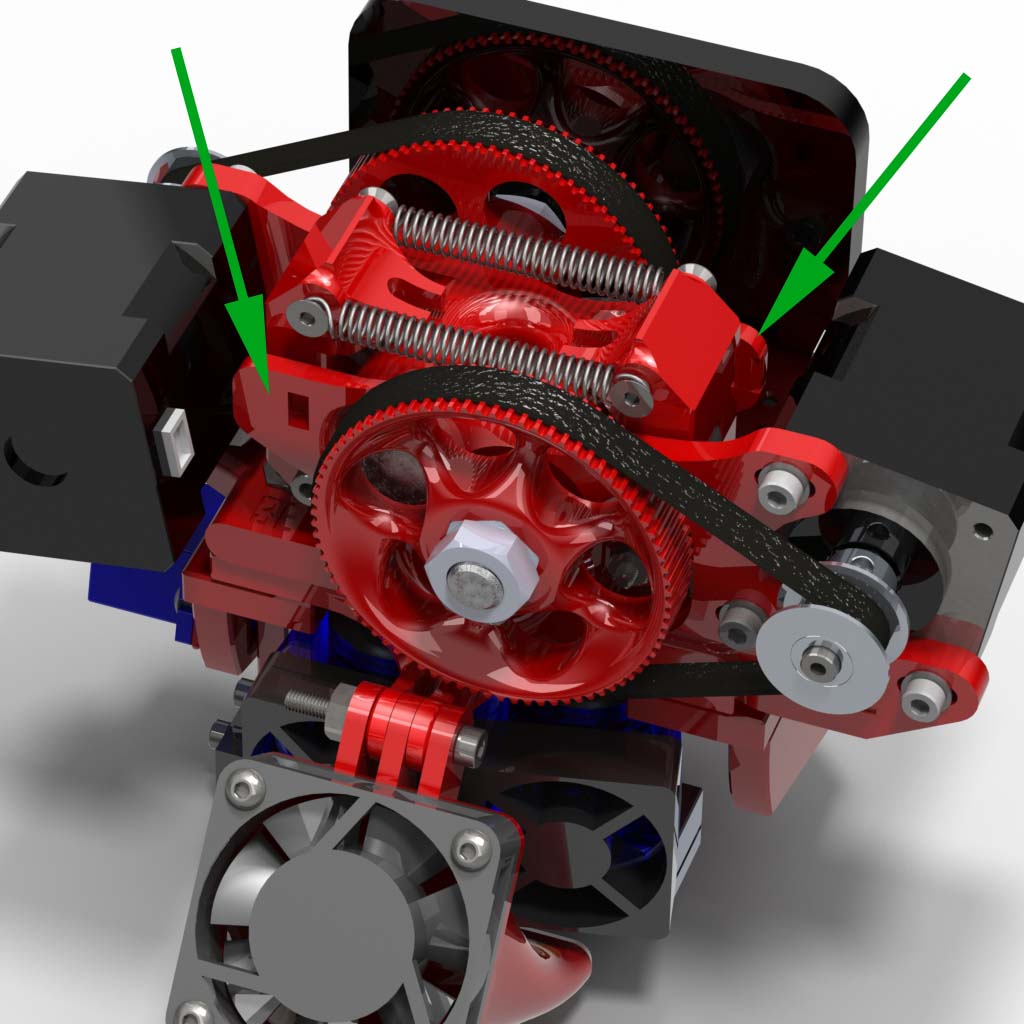
- Install an idler block on each side of the extruder with an M3x25 screw and an M3 nut.
- Install the extension springs between the anchor screws at the top of the idlers. A pair of needle-nose pliers or a hook can make this easier.
- You can substitute our light springs for the ones that came in the hardware kit if you wish to print with flexible filament.
|
X Carriage
 |
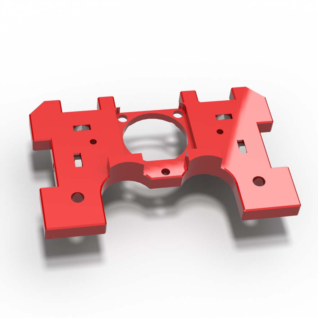
- Press four M3 hex nuts into the shelf using needle-nose pliers.
|
 |
- Install a 25x25x10mm fan into the shelf with three M3x12 flat head screws. Tap the holes in the fan or squeeze the plastic with pliers so the screw threads will grip.
|
 |
- Install the hexagon fan shroud with two M3x6 button head screws.
|
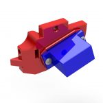 |
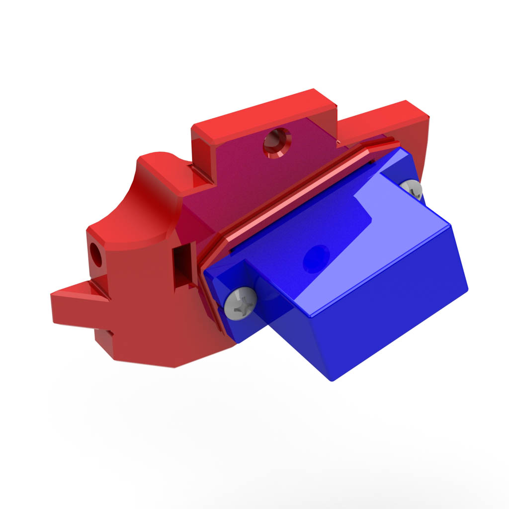
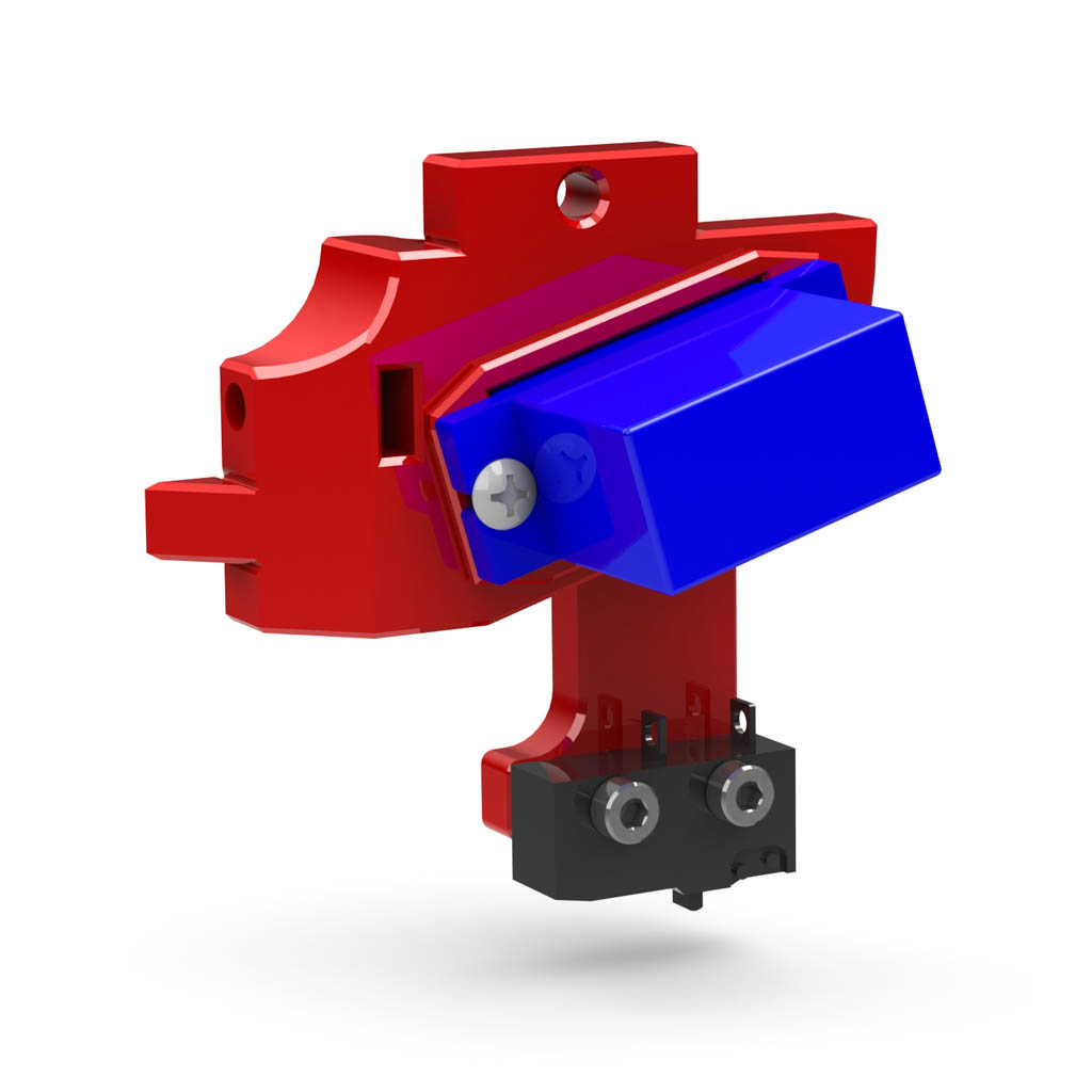
- Press an M3 nut into each shelf bracket.
- Install an HXT900 servo into the left bracket using the screws that came with the servo.
- You may install the printed servo spacer under the servo to provide more clearance between the probe arm and the hot end. This may be necessary, depending on how you orient the heat blocks.
|
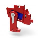 |
- Press a servo arm into the Z probe.
- Install the probe onto the servo using the screw that came with the servo.
|
 |
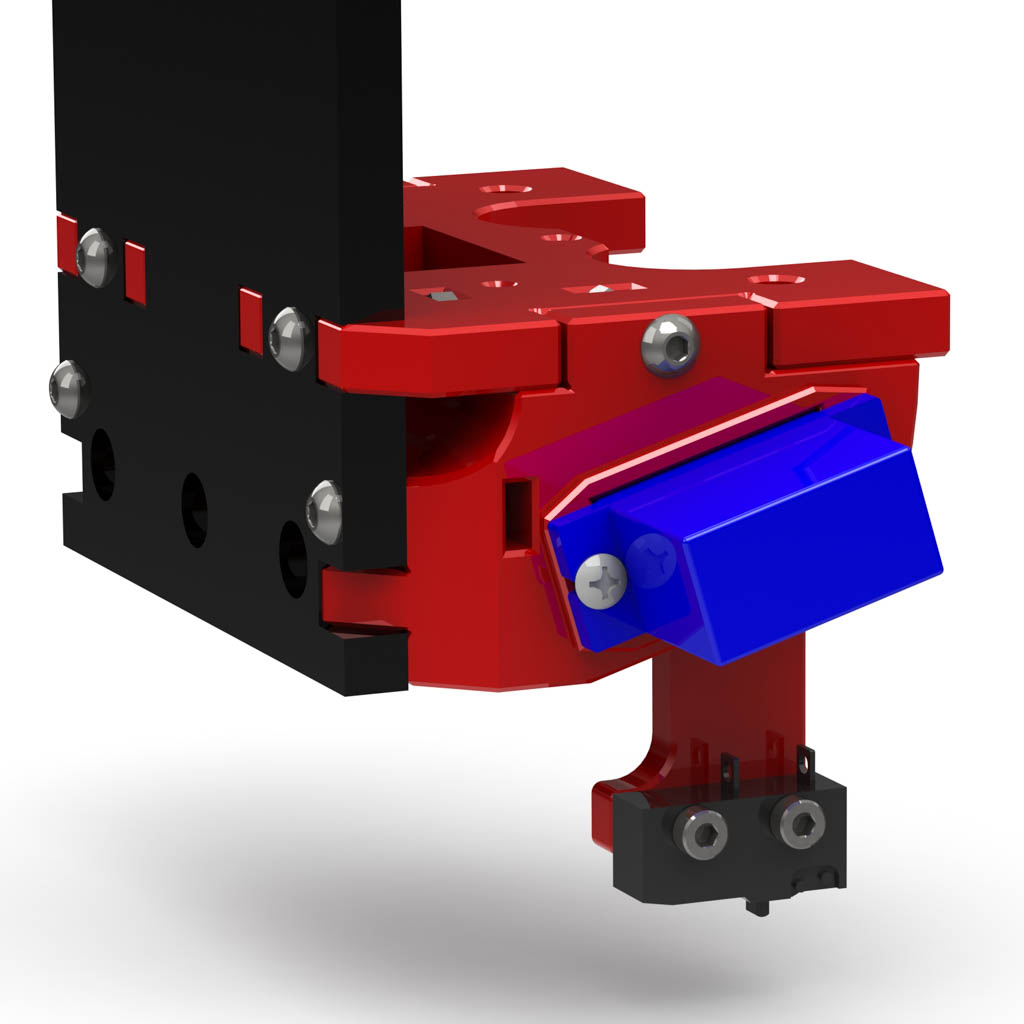
- Mount the snap switch to the Z probe with two M2.5×10 screws.
|
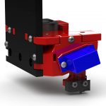 |
- Mount the shelf and brackets to the printer back plate using six M3x16 button head screws.
|
Final Assembly
 |
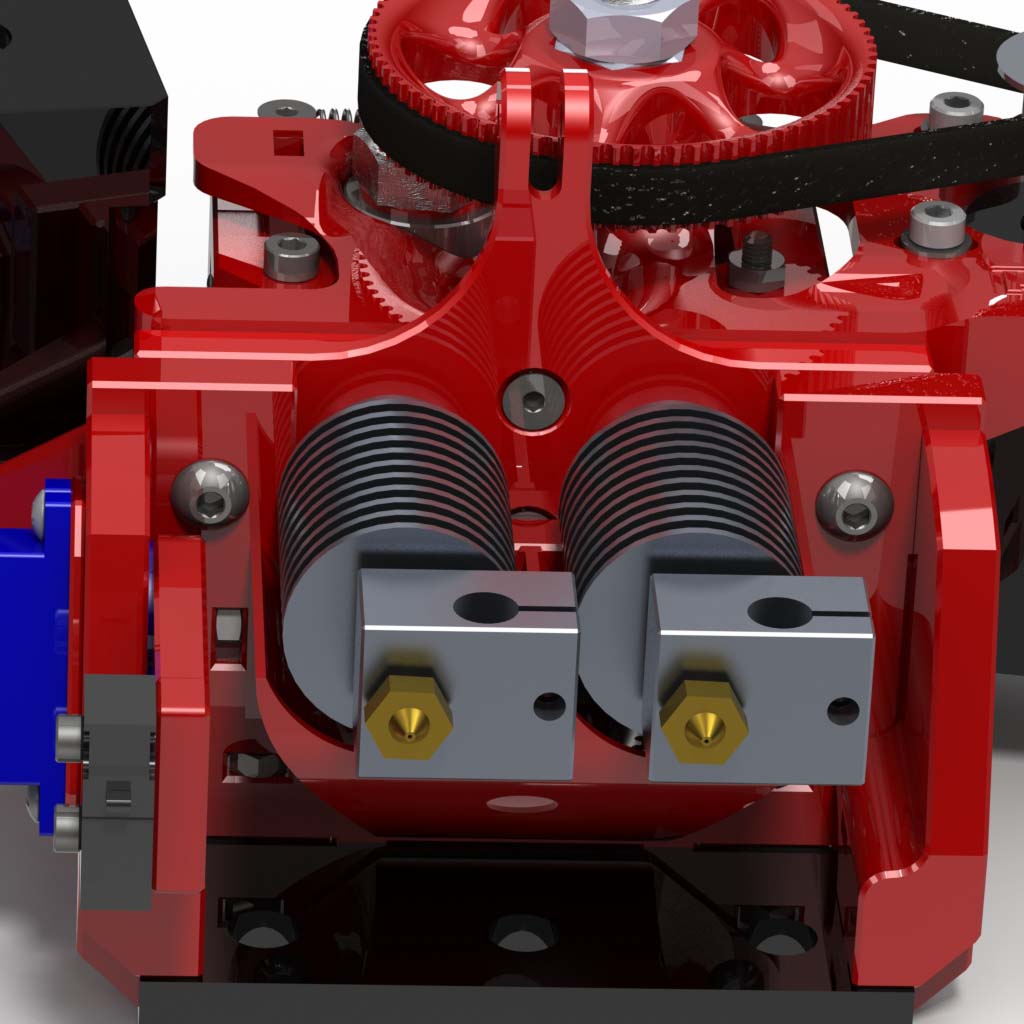
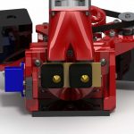
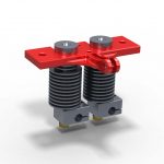
- Install two hot ends into the double groove mount.
|
 |
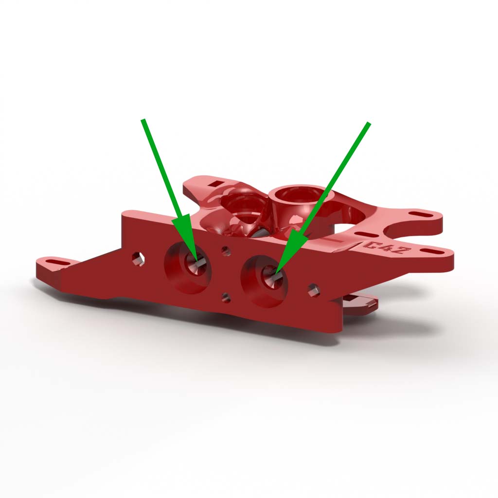
- Install the groove mount on the extruder block with two M3x12 flat-head screws.
- Do not tighten the screws. Just install them for now. You can tighten them later to bring the nozzles closer together if needed.
|
 |
- Slide the extruder assembly with the hot ends onto the shelf and secure it with two M4x20 button head screws.
- If you cannot reach the left M4x20 screw head to tighten it, you can temporarily remove the left shelf support, complete with the servo and arm and reinstall it afterward.
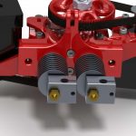
- If the tips of the hot ends are not exactly 27mm apart, you can adjust them by removing the assembly and adjusting the screws in the groove mount. Tightening them will move the nozzles closer together. Loosening them will move them further apart. Reinstall the assembly to check your adjustment.
|
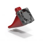 |
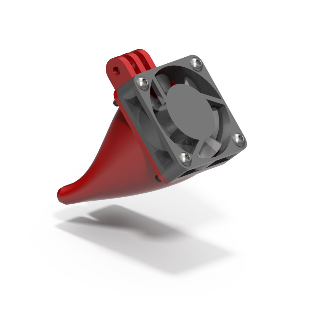
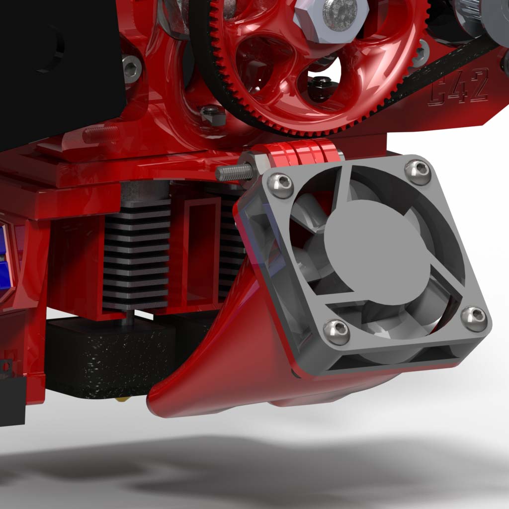
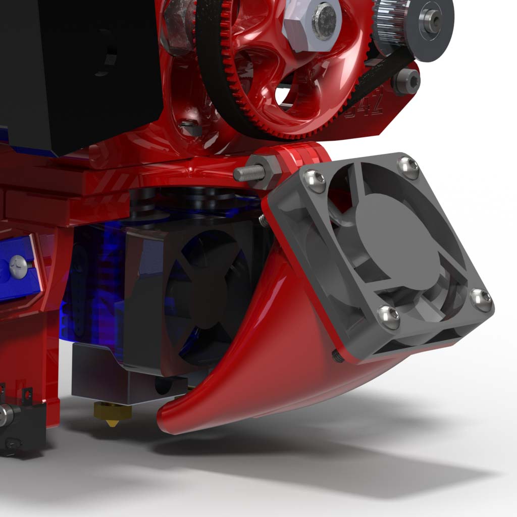
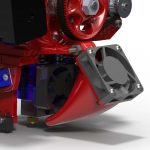
- Install a 40x40x10mm fan on the print cooling shroud using four M3x16 button head screws.
|
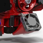 |
- Mount the print cooling fan shroud on the extruder with an M3x25 screw and M3 nut.
|
 |
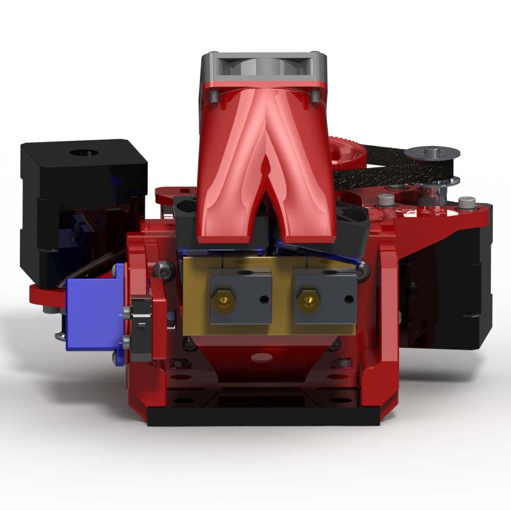
- Make sure the heater blocks on your hot ends are oriented so the blocks and heater wires will not interfere with the Z probe.
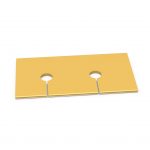
- Use sharp scissors to cut slits and small round holes in the insulator so it will fit around the hot ends. The slits should be 27mm apart. Make sure the insulator will cover the tops of the heat blocks and will not interfere with the Z probe.
|
 |
- Install the insulator between the fan shroud and the heater blocks. Insert it from the rear so you can see the slits in the front and ensure that they are closed.
|
Wiring
 |
- Wiring tie-down points are provided on both sides of the extruder block. All of the wires for the hot end heaters, thermistors, motors, fans, servo and limit switch can be bundled together and tied to these points with plastic zip ties.
|
Printed Part Cleanup
 |
- Remove support material from the filament channels in the main extruder block.
|
 |
- (Optional) Tap two holes in the X carriage shelf with M3x0.5 threads. If you don’t have an M3 tap, you may be able to form threads in the part by forcing in an M3 screw. You may need to drill the holes out first, depending on your printer.
|
|
- (Optional) Tap two holes in each idler block with M3x0.5 threads. If you don’t have an M3 tap, you may be able to form threads in the part by forcing in an M3 screw. You may need to drill the holes out first, depending on your printer. Be careful not to split the part, as the holes are parallel to the layers.
|
|
-
- (Optional) Tap four holes in the cooling fan shroud with M3x0.5 threads. If you don’t have an M3 tap, you may be able to form threads in the part by forcing in an M3 screw. You may need to drill the holes out first, depending on your printer.
|
|
- Clean out the two countersink holes in the bottom of the double groove mount. Make sure M3 flat-head screws will fit flush with the surface.
|
|
- (Optional) Tap four holes in the Z probe arm with M2.5×0.45 threads. Your switch will only use two of the four holes. If you don’t have an M2.5 tap, you may be able to form threads in the part by forcing in an M2.5 screw. You may need to drill the holes out first, depending on your printer.
|
Idler Blocks
|
- Insert an idler pin into a 688ZZ bearing and insert it into one of the idler blocks. You may need to round sharp edges on the pin, depending on how well your printer controls the first layer.
|
|
- Insert a sharp tool into one of the holes in the idler pin and rotate it to lock it into place. A scratch awl works well for this.
- Repeat for the other pin and idler block.
|
|
- Install two M3x12 flat head screws. These are the anchor points for the extension springs.
|
Extruder Block
|
- Press two M4 nuts and two M3 nuts into the base of the extruder block. These will serve as anchors for the mounting and groove mount tensioning screws.
|
|
- Press four 688ZZ bearings into the extruder block. You may need to clean out the bearing seats, depending how well your printer prints overhangs.
|
|
- Install a 1mm spacer onto each hobbed bolt. The beveled side goes toward the bolt head.
- Install the hobbed bolts into the extruder block.
- Install a 2mm spacer on the threaded end of each bolt after it is inserted.
|
|
- Press one of the jam nuts that came with each hobbed bolt into each pulley.
- Install the pulleys on the hobbed bolts.
- Adjust each pulley so the bolt turns freely but has no end play and lock it in place with a jam nut.
|
|
- Install the motors with six M3x8 screws and six M3 washers. Leave the screws loose for now.
|
|
- Install a 20-tooth pulley on each motor.
- Slip a belt over the small pulley first, side the motor up and slip it onto the large pulley; repeat for the other side.
- Adjust the belt tension by moving the motor and tighten the motor screws. The belt does not stretch, so it doesn’t need to be taut. Just take out the slack.
|
|
- Install an idler block on each side of the extruder with an M3x25 screw and an M3 nut.
- Install the extension springs between the anchor screws at the top of the idlers. A pair of needle-nose pliers or a hook can make this easier.
- You can substitute our light springs for the ones that came in the hardware kit if you wish to print with flexible filament.
|
X Carriage
 |
- Press four M3 hex nuts into the shelf using needle-nose pliers.
|
 |
- Install the E3Dv6 fan shroud with two M3x6 button head screws.
|
|
- Press an M3 nut into each shelf bracket.
- Install an HXT900 servo into the left bracket using the screws that came with the servo.
- You may install the printed servo spacer under the servo to provide more clearance between the probe arm and the hot end. This may be necessary, depending on how you orient the heat blocks.
|
|
- Press a servo arm into the Z probe.
- Install the probe onto the servo using the screw that came with the servo.
|
|
- Mount the snap switch to the Z probe with two M2.5×10 screws.
|
 |
- Mount the shelf and brackets to the printer back plate using six M3x16 button head screws.
|
Final Assembly
 |
- Install two hot ends into the double groove mount.
- If you are using 1.75mm hot ends with liners, insert the liners
|
 |
- Install the groove mount on the extruder block with two M3x12 flat-head screws.
- If you are using liners, insert them up into the block and trim to length.
- Do not tighten the screws. Just install them for now. You can tighten them later to bring the nozzles closer together if needed.
|
 |
- Slide the extruder assembly with the hot ends onto the shelf and secure it with two M4x20 button head screws.
- If you cannot reach the left M4x20 screw head to tighten it, you can temporarily remove the left shelf support, complete with the servo and arm and reinstall it afterward.
- If the tips of the hot ends are not exactly 27mm apart, you can adjust them by removing the assembly and adjusting the screws in the groove mount. Tightening them will move the nozzles closer together. Loosening them will move them further apart. Reinstall the assembly to check your adjustment.
|
|
- Install a 40x40x10mm fan on the print cooling shroud using four M3x16 button head screws.
|
 |
- Snap the E3Dv6 cooling fans and shrouds onto the front of the hot ends. The lip of the fan shrouds should hang downward.
- NOTE: the E3Dv6 fan shrouds should fit into the printed shroud behind the hot ends so the warm exhaust air will exit out the top, behind the extruder.
- Mount the print cooling fan shroud on the extruder with an M3x25 screw and M3 nut.
|
|
- Make sure the heater blocks on your hot ends are oriented so the blocks and heater wires will not interfere with the Z probe.
- Use sharp scissors to cut slits and small round holes in the insulator so it will fit around the hot ends. The slits should be 27mm apart. Make sure the insulator will cover the tops of the heat blocks and will not interfere with the Z probe.
|
 |
- Install the insulator between the fan shroud and the heater blocks. Insert it from the rear so you can see the slits in the front and ensure that they are closed.
|
Wiring
 |
- Wiring tie-down points are provided on both sides of the extruder block. All of the wires for the hot end heaters, thermistors, motors, fans, servo and limit switch can be bundled together and tied to these points with plastic zip ties.
|
Next Steps
Firmware and Calibration instructions are available here:
Marlin Firmware Setup
Double Extruder Calibration
 Make sure you have everything you need: