We provide preconfigured firmware for MakerFarm i3v printers using RAMPS 1.4 electronics. Versions are available for all of our extruders. These instructions walk through the basic steps to download the firmware, configure it for your printer and get printing.
This tutorial assumes you are using Windows 7 or 8. If you are using a Mac, most of these instructions will work, but the COM port selection is different.
Before You Begin
You should already have your extruder assembled. If you’re using one of our double extruders, instructions are here:
Download Arduino IDE
The Marlin firmware is built using the Arduino IDE (Integrated Development Environment). You will need to download and install this free software to be able to upload firmware to your printer. We did our testing with version 1.0.5. Other versions may work.
Download the Arduino software here:
You will need to click on “Previous Releases” if you want to download version 1.0.5.
Download Marlin Firmware
You will also need to download the Marlin firmware. You can download it directly from the Marlin web site if you wish. We provide versions that are preconfigured and tested with all of our extruders:
Itty Bitty Belted Extruder: i3v_itty_bitty.zip
Itty Bitty Double Extruder: i3v_double_bitty.zip
Itty Bitty Double Flex Extruder: i3v_double_flex.zip
Download the version for your extruder and unzip it somewhere on your computer.
Set up the Arduino IDE
To compile and upload firmware to your printer, you will need to set up the Arduino IDE project for the COM port and board you are using.
- Plug your printer into a USB port on your computer.
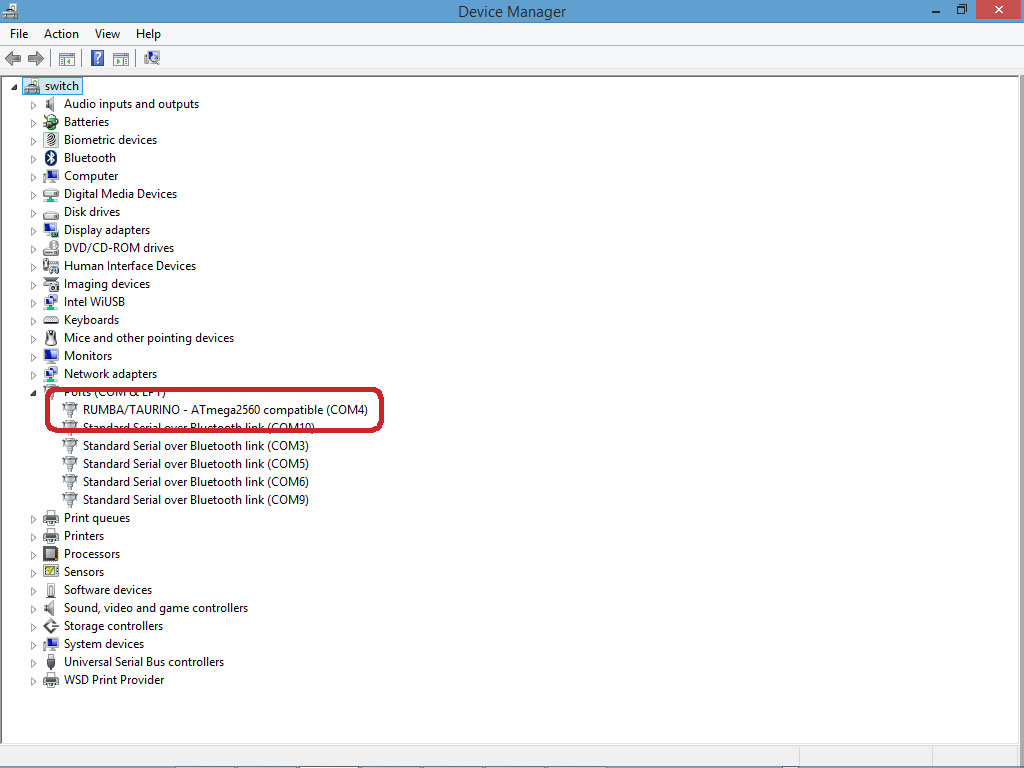
- Open Device Manager to determine which COM port your printer is using.
- Press the Windows key, type “device manager” and press enter
- When device manager opens, expand the “Ports” section.
- Find the printer device. MakerFarm RAMPS boards appear as “RUMBA/TAURINO – ATmega2560 compatible”
- Make a note of the com port for the device.
- Open the folder where you downloaded and extracted the firmware zip file
- Open the Marlin sub-folder and double-click on the file Marlin.ino to open the Arduino IDE.
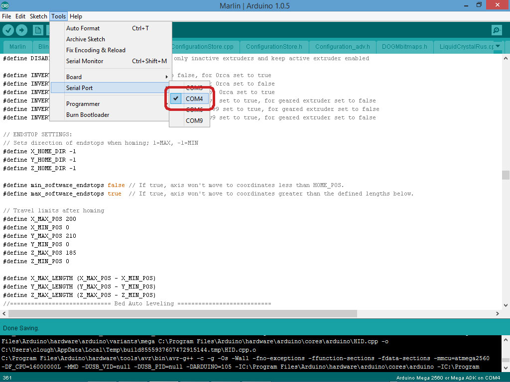
- In the Arduino IDE, select the Tools->Serial Port menu and select the COM port you determined above. The tools menu can be very slow to open, depending how many COM ports you have on your computer.
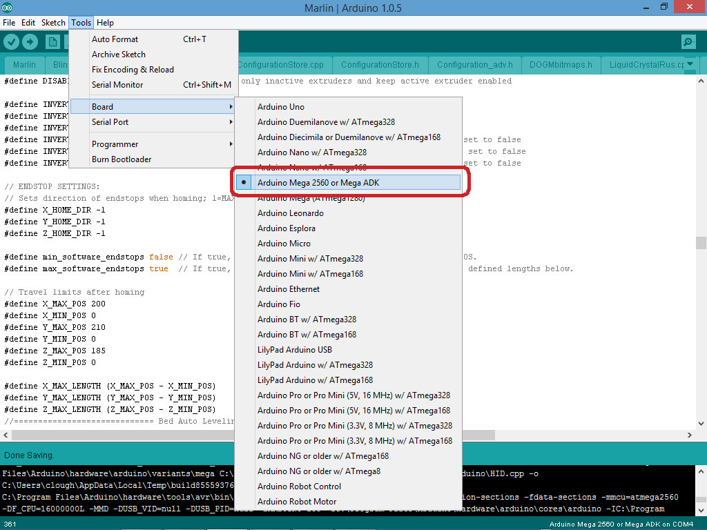
- Select the Tools->Board menu and select “Arduino Mega 2560 or Mega ADK.”
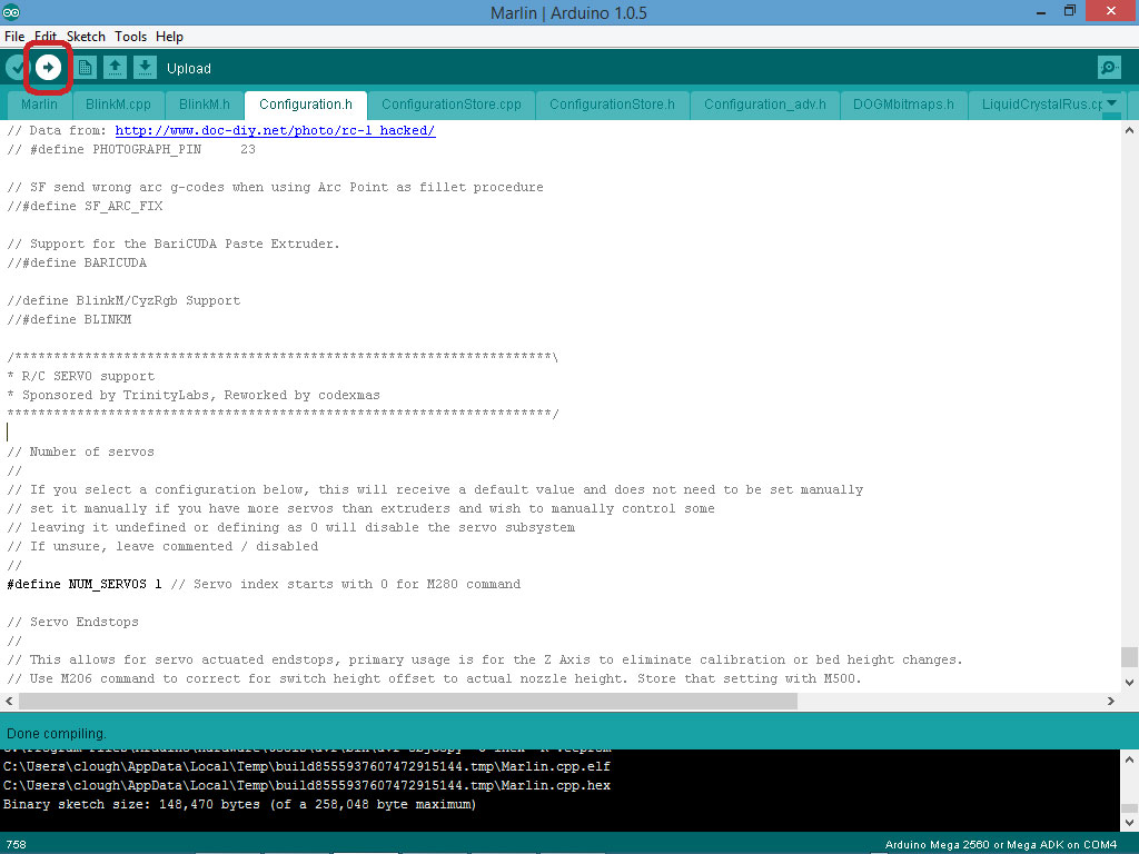
At this point, you should be able to click the check-mark button located just below the File menu and the firmware should compile successfully. Messages will scroll by in the window at the bottom of the screen, and at the end you should see something like “Binary sketch size: 148,472 bytes (of a 258,048 byte maximum)”. Your numbers may be different. If you get this message, you’re ready to move on to the next step.

Initial Configuration
To customize the firmware for your printer, you will need to edit the “Configuration.h” file. In the Arduino IDE, this is usually the fourth tab from the left. Select the tab to view and edit the contents of the file.
Our preconfigured firmware downloads, above, have most of the customizations already made for you, but there are a few things that will vary from printer to printer.
Motherboard
In the Configuration.h file, find the following lines:
#ifndef MOTHERBOARD
#define MOTHERBOARD 34
#endif
If you are using RAMPS electronics with the recommended electrical connections, you probably won’t need to touch this. If you are using something else, you will need to select the appropriate board.
E-Steps
Depending which extruder bolts you’re using, you may need to adjust the E-Steps value for proper extrusion. If you’re using our hobbed bolts in an Itty Bitty extruder, we recommend starting with a value of 615 steps/mm. This assumes you are using the usual 1/16 microstepping and your extruder has a 4:1 drive ratio. All of the Itty Bitty extruders have a 4:1 drive.
#define DEFAULT_AXIS_STEPS_PER_UNIT {80, 80, 4000, 615.0}
Bed Size
In the Configuration.h file, find the following lines:
// Travel limits after homing
#define X_MAX_POS 200
#define X_MIN_POS 0
#define Y_MAX_POS 210
#define Y_MIN_POS 0
#define Z_MAX_POS 185
#define Z_MIN_POS 0
Adjust these values to reflect the size of your printer’s bed. The preconfigured values will work for an 8″ bed.
You will note in the example that we set the Y MAX position a little higher. This allows us to position the hot end off the front of the bed for purging. You may choose to do this, but you will need to determine how far you can move your bed in the Y direction without hitting the mechanical limits.
Probe Offsets
This section of the Configuration.h file tells the firmware where the Z probe is located, relative to the zero point of the X carriage. If you are using our preconfigured firmware, these values will get you started, but you will likely need to adjust the Z offset once you start tuning the bed leveling.
 // these are the offsets to the probe relative to the extruder tip (Hotend - Probe)
 #define X_PROBE_OFFSET_FROM_EXTRUDER 34.5
 #define Y_PROBE_OFFSET_FROM_EXTRUDER -5
 #define Z_PROBE_OFFSET_FROM_EXTRUDER -2.00
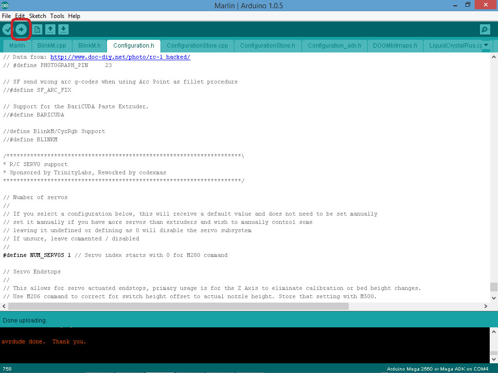
Compile and Upload
Now that your configuration is complete, it;s time to upload. Click the arrow button at the top of the Arduino window to compile and upload the firmware. When the process is complete, you should see the message “avrdude done. Thank you.” at the bottom of the screen.
Clear and Save EEPROM
All of our firmware is configured to save values in EEPROM so you can adjust values from the LCD. After uploading new firmware, you will need to reset the configuration to factory defaults and save these values to the EEPROM or the printer may behave strangely.
Use your favorite tool (Pronterface, Octoprint, etc.) to send M502 followed by M500 to the printer. You should see the following if everything works:
>>>M502
SENDING:M502
echo:Hardcoded Default Settings Loaded
>>>M500
SENDING:M500
echo:Settings Stored
Adjustments
Congratulations. You’ve uploaded firmware to your printer. Now it’s time to adjust a few things.
Adjust Servo Endpoints
For the firmware to deploy and retract the Z probe, it needs to know the proper values to send to the servo for the deployed and retracted positions. The easiest way to find these values is to use the M280 command to experiment with different values. Send the following GCODE to the printer:
M280 P0 S100
This command should move the servo to a position somewhere in the middle of its travel. The last number (100) is the servo position. Keep increasing and decreasing this value until you find the correct values for the deployed (exactly vertical) and stowed probe positions.
Assume that we find that a value of 143 deploys the probe vertically and 40 stows it out of the way. Set these values in Configuration.h near the end of the file:
// Servo Endstops
//
// This allows for servo actuated endstops, primary usage is for the Z Axis to eliminate calibration or bed height changes.
// Use M206 command to correct for switch height offset to actual nozzle height. Store that setting with M500.
//
#define SERVO_ENDSTOPS {-1, -1, 0} // Servo index for X, Y, Z. Disable with -1
#define SERVO_ENDSTOP_ANGLES {0,0, 0,0, 143, 40} // X,Y,Z Axis Extend and Retract angles
The fifth value is the deployed position and the sixth (last value) is the stowed position for the Z probe.
After changing these values, you must compile and upload the firmware again before continuing.
Once you have uploaded the firmware, you should be able to deploy and retract the Z probe with the following commands:
M401 // deploy
M402 // retract
Roughly Calibrate the Z Offset
The Z offset in the preconfigured firmware will get you close, but you will need to test and adjust it before proceeding to final calibration.
It’s time to run your first auto-level. Using Pronterface (or your favorite tool) run the following GCODE commands:
G28 // home
G29 // detailed z probe
This should cause the printer to home the X and Y axes, probe the Z axis once in the middle of the bed and then probe the bed in nine places to establish a bed leveling matrix.
The following must be performed immediately and without homing the printer. If you wait too long, or if you home the bed, the motors will time out, you will lose the bed level and have to start over with the GCODE above. When you move in the X direction, you should see the Z screws moving a little bit, too. This tells you that the auto bed leveling is active.
- Use Pronterface (or your favorite tool) to move the extruder to the center of the print bed.
- Lower the nozzle very carefully until the tip of the nozzle just barely grips a piece of paper sitting on the bed. This is your zero point. If you have two nozzles, keep track of them both and stop when either one grips a piece of paper.
- Read the Z position off the LCD. In this example, it’s 0.32mm.

If your Z position reads zero, you’re done. But it probably won’t, so you’ll need to subtract the actual Z value from your Z offset. Note that this can be a little confusing because the Z offset in the Configuration.h file is a negative number, but it is shown as a positive number on the LCD. We will use the positive numbers from the LCD to keep things simple.
The final position where the printer grips the paper may be a negative number. Make sure to enter the negative into the calculator, or you will get strange results.
Use this calculator to determine your new Z offset value:
You can change the Z offset value from the LCD menu, under Control->Motion->Z Offset. After you change it, you will need to save the values to EEPROM. The LCD command to do this is under Control->Store Memory.
Repeat the G28/G29 commands and check until it just grips the paper at zero.
Next Steps
If you just have a single extruder, you should now be good to go. Do some test prints and fine-tune your Z offset if needed.
If you have a double extruder, you’ll need to calibrate it: