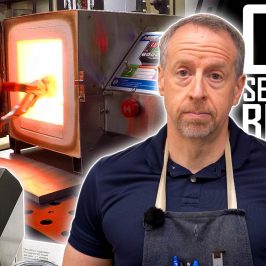
I have always wanted a toolpost grinder for my lathe. As we’ve built out the shop here at Clough42, I’ve made more than a few arbors for drill chucks, face mills, boring heads, slitting saws and other cutting tools. They work well, but they can never be quite as awesome as their commercially-produced counterparts because I have no way to grind on the lathe. And without a way to grind, heat treatment is really out of the question. So I’ve settled for making the parts out of 1144, also known as StressProof steel. 1144 is great stuff–it’s tough, it’s wear-resistant and it doesn’t warp as you cut it. It’s what you use if you can’t heat-treat and grind.
That’s going to change.
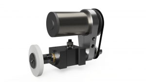
After shopping around and looking at prices, I’ve decided to build my own toolpost grinder. This video is part one of a series showing the process as I build a toolpost grinder from scratch. In part one, I go over the core parts of the grinder and show the details of the design. None of this exists yet. I don’t have a grinder that I prepared earlier to show you. We’ll go through the build together, and you’ll get to see each step along the way.
Because of the size of my lathe (Grizzly G0602) the spindle needs to be compact. I want to be able to mount it on top of the compound so I can grind tapers, and that means the outside diameter of the spindle housing can’t exceed an inch and a half. Over that, and I won’t be able to clamp it and mount it on center without taking off the top slide.
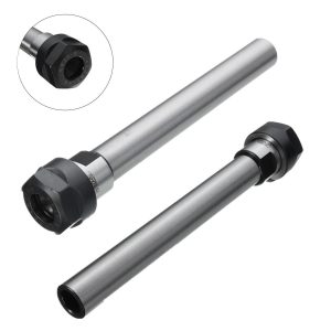
I also want to be able to grind inside as well as outside diameters and tapers. That means I need a collet arrangement to hold mounted points, and I also need a way to mount a wheel. I think the easiest way to do that is with an ER collet holder for inside jobs and tapered wheel arbors that fit into the collet taper for grinding outside surfaces. It would be great to turn a collet holder out of alloy steel, heat treat it and grind it to final dimensions. But of course I don’t have a toolpost grinder yet, so I’ll have to settle for a commercially-available collet holder.
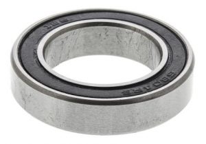
The spindle will also need some bearings. Ideally, the best bearings to use for a high-speed spindle are angular contact ball bearings. Given the 20mm diameter of the collet holder and the need to keep the outside of the spindle housing to a mere 1.5 inches, this one is tough. I couldn’t find readily-available angular-contact bearings that would fit those dimensions. I decided instead to use deep-groove sealed ball bearings. They should be more than enough in this application. 6804-2RS bearings will fit, and they provide a dynamic radial load capacity of about 900lbs. You can figure the allowable static radial load is around 500lbs, and the axial load capacity is about half of this, or 200-250lbs. That should be more than enough in this application.
That’s enough for now. Watch the video for a full overview of the design. Next time, we’ll start making some chips.
If you want to build one for yourself, here are some links to the parts I used:
*This site contains affiliate links for which I may be compensated
- C20-ER20A-150L Collet Holder (eBay*): https://goo.gl/xufUxa
- 6805-2RS Deep Groove Ball Bearings (eBay*): https://goo.gl/GuCyHu
- Belleville Disc Springs (McMaster-Carr): https://goo.gl/rQZXJm
- 140J2 Poly V-Belt (VBeltSupply): https://goo.gl/CCkP4Y


