Today we’re making a set of low-profile clamping jaws, similar to Mitee-Bite Talon Grips.
When CNC milling complex parts, it’s often most convenient to use stock a little bit thicker than the finished part so we can hold on to the bottom edge and mill away the entire perimeter of the part in a single operation. Then we can flip the part, possibly holding it in soft jaws and face the extra material off.
The challenge is to get a solid grip on the material with the vise jaws. Too little grip and the part might come free while roughing out the material. Too much, and we’re just wasting material. The solution is vise jaws with teeth that securely grip the bottom edge of the material with enough force to hold it during the heaviest milling operations.
The ones we’re building today only extend .060″ above the bottom edge of the stock, minimizing material waste.
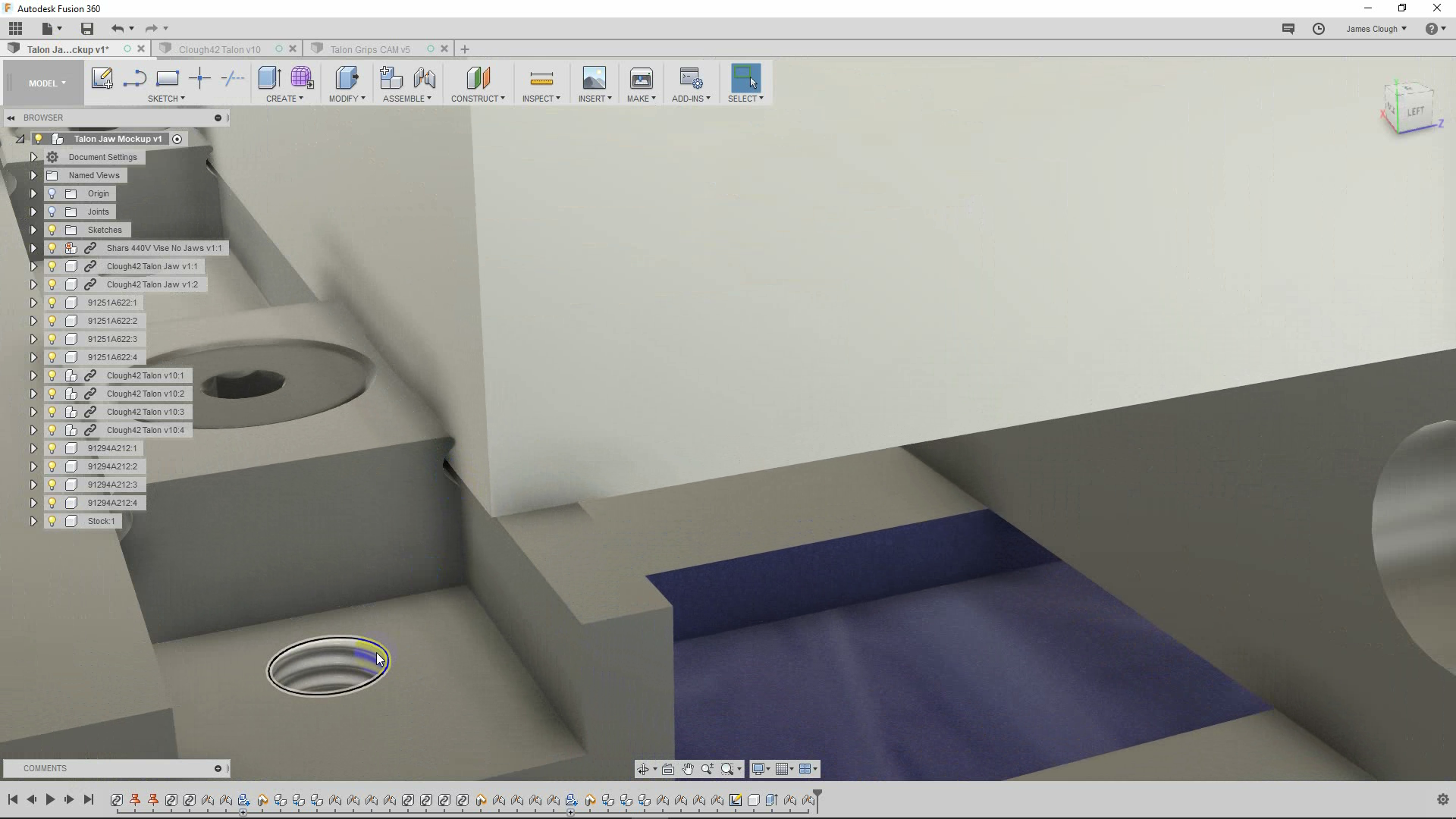
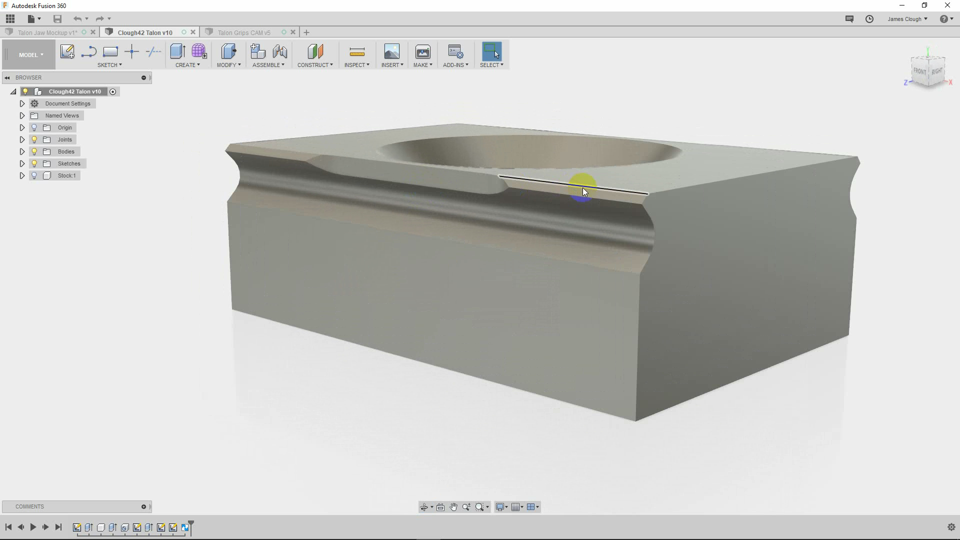
The Design
When the whole project is finished, we’ll have a pair of jaws and four grippers. The grippers are held into the vise jaws with M5 screws and can be installed in several different configurations, depending on the needs for a particular setup.
The grippers are small blocks of tool steel with a groove and two teeth on each side and a countersunk screw hole through the center.
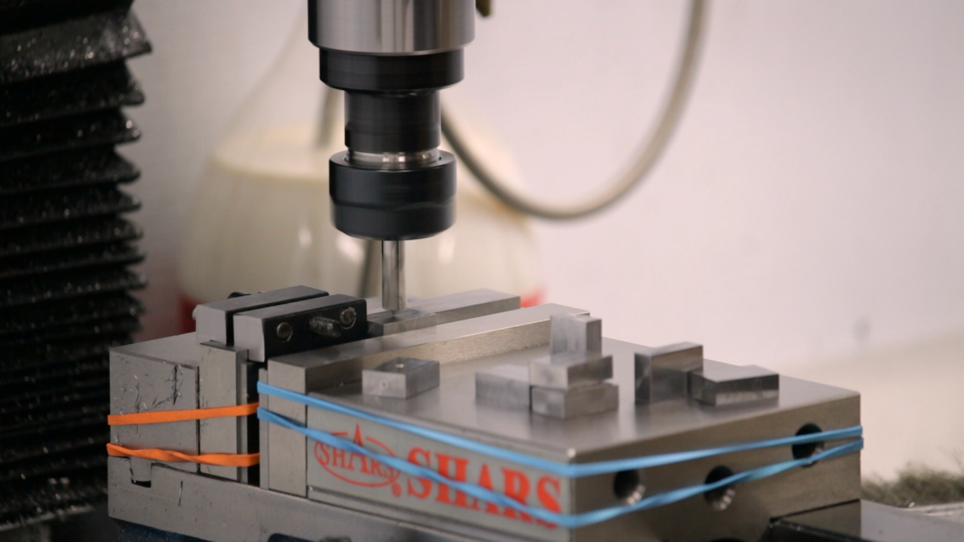
Making the Blanks
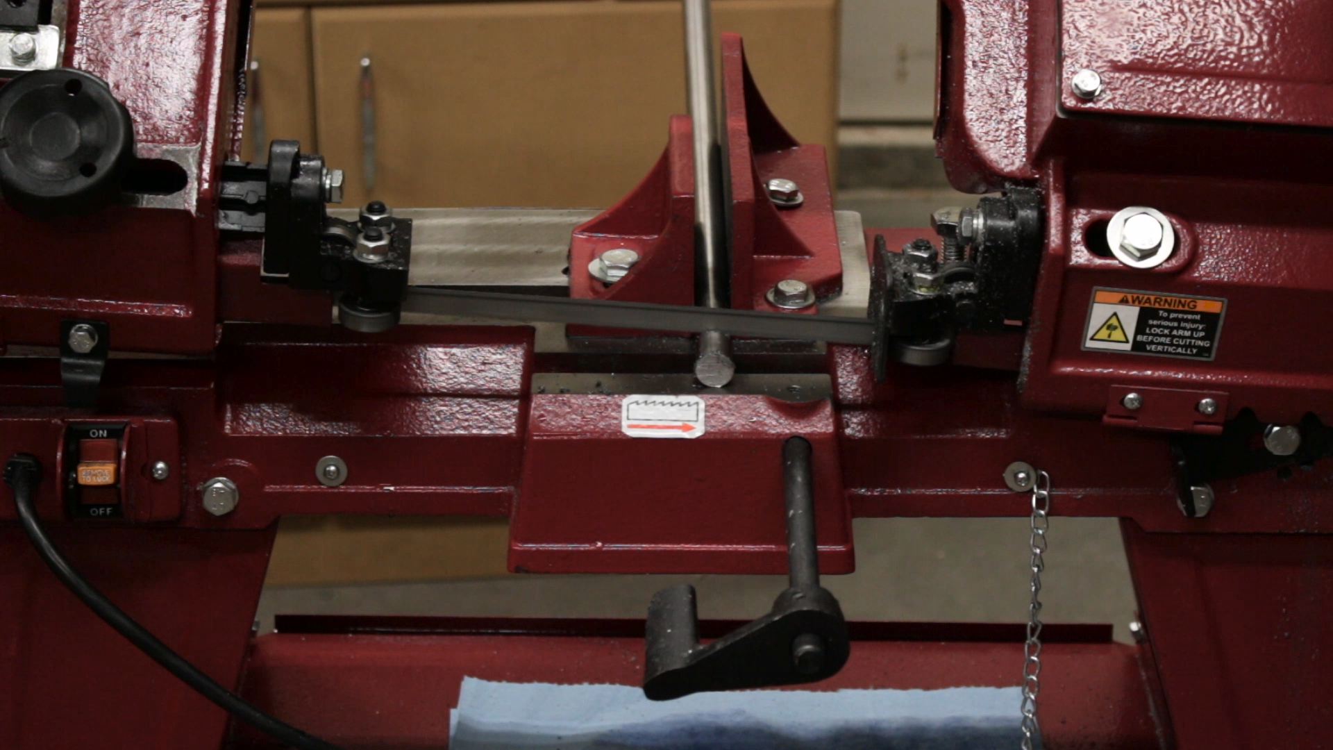
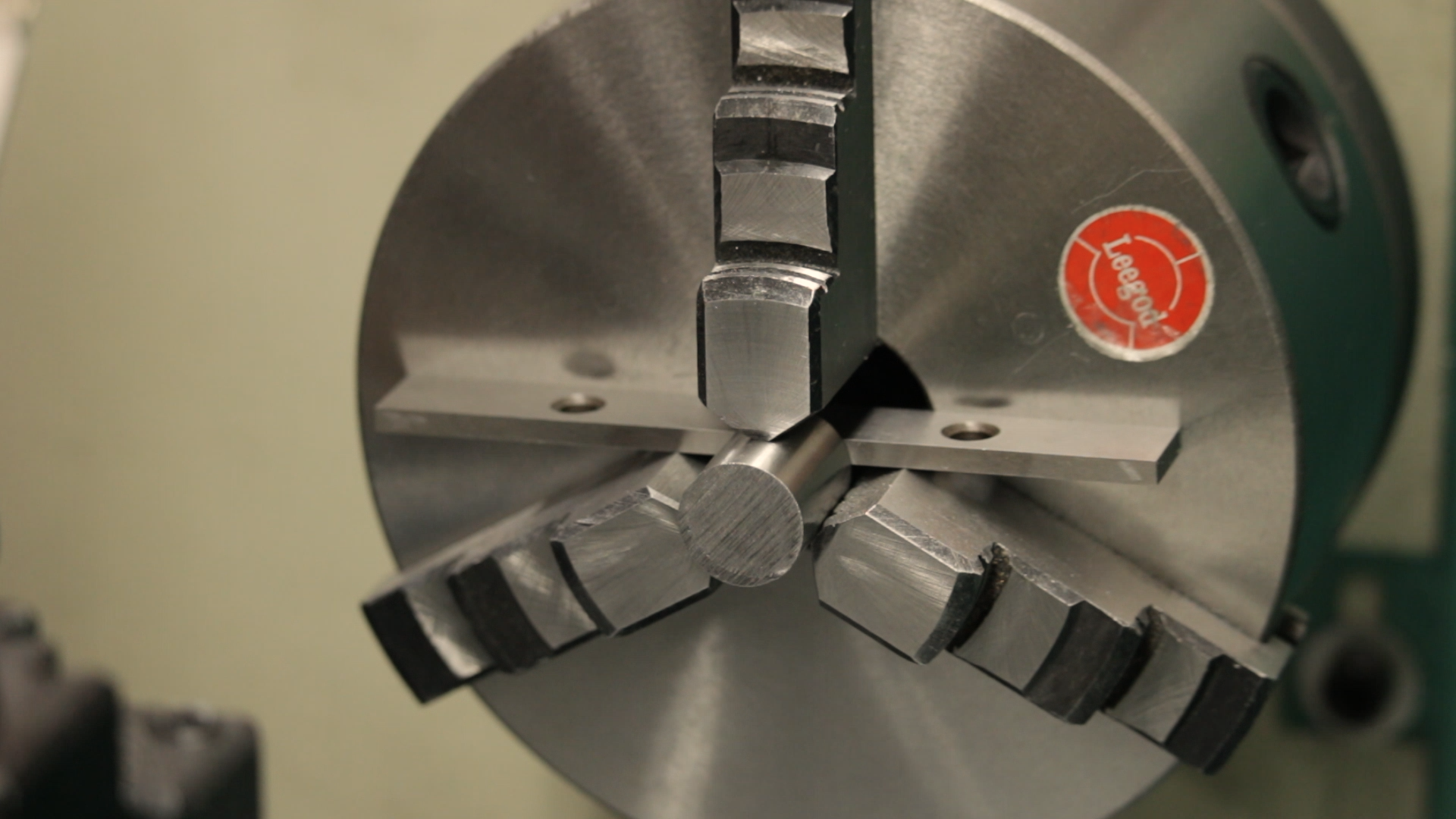
I didn’t have any flat ground tool steel on hand, so I decided to use W1 drill rod. I cut off some chunks at the bandsaw and squared them up using the mill and lathe.
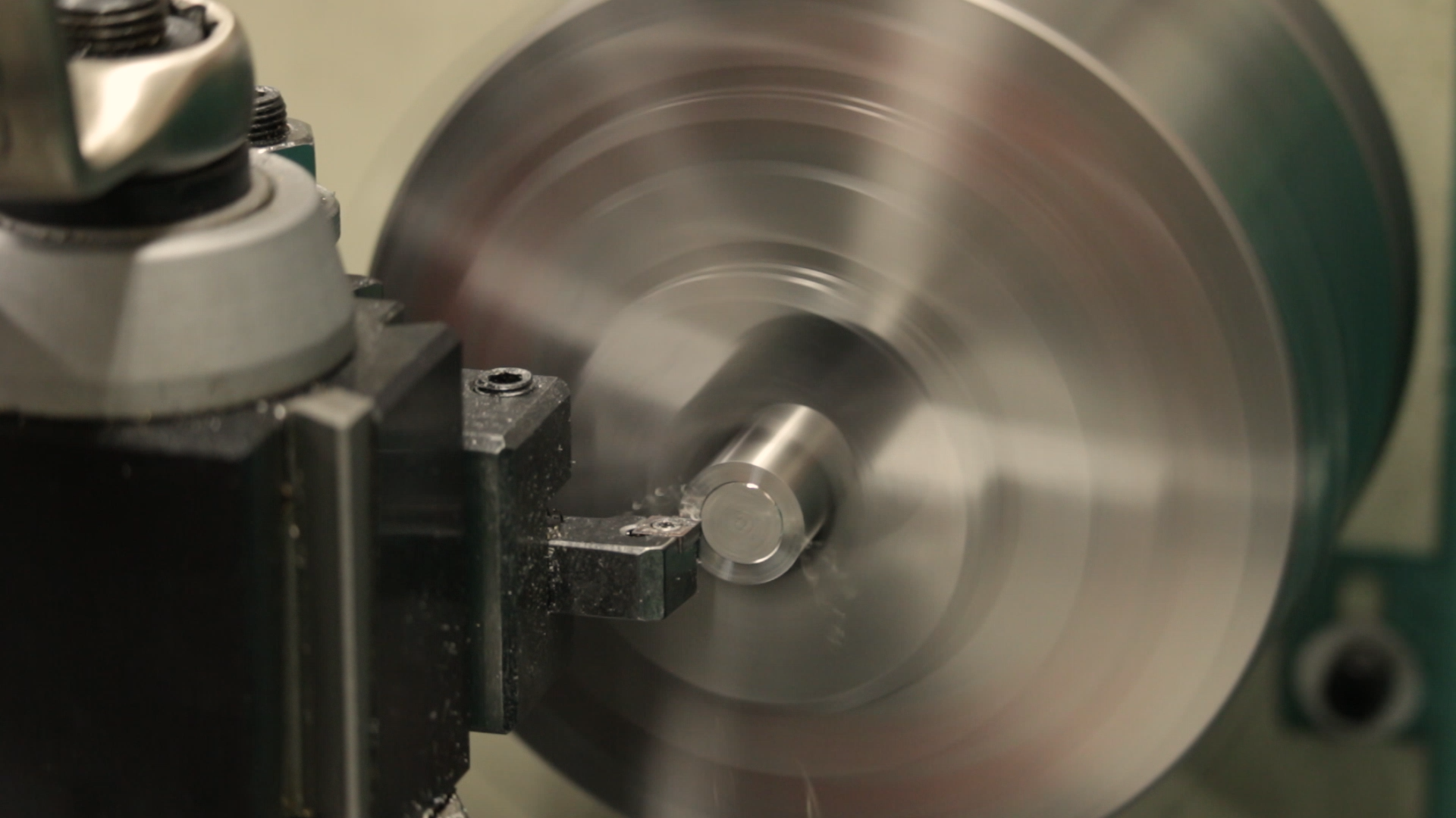
I could have done all of the squaring in the mill, but after flattening four sides, the parts would still need to be trimmed to length. This would take two additional setups in the mill and require multiple side milling passes to get them to length. I really despise side milling stock to length, so I decided to just face them to length in the lathe while they were still round.
After facing to length, the parts could be clamped by the ends in the mill vise for squaring. The sequence is:
- Face one side of the cylinder.
- Place the one face side down on parallels and face the other side to thickness.
- Stand the blank on edge on one parallel in the vise and mill one edge
- Flip the blank and mill to width.
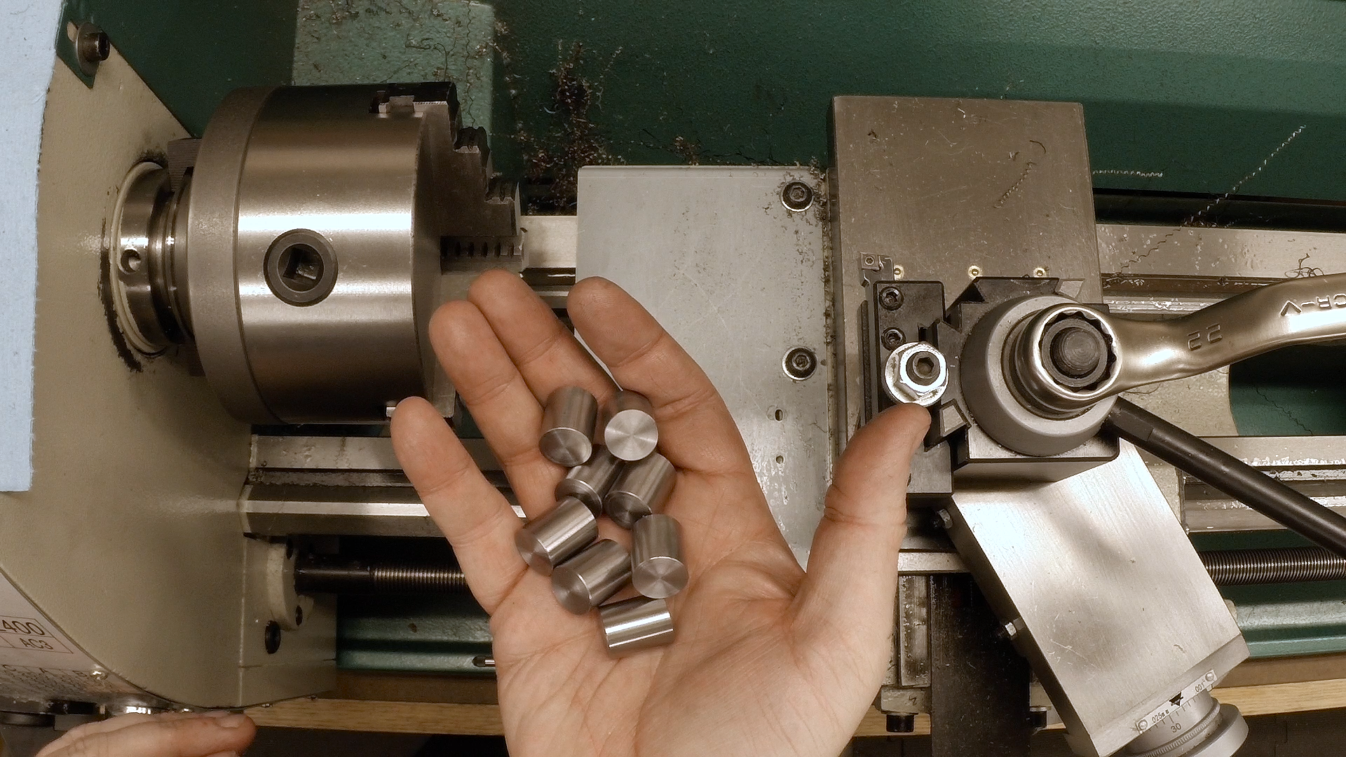
I decided to start with eight blanks because I need six parts. If this logic doesn’t make sense to you, then you’re much better at this than I am.
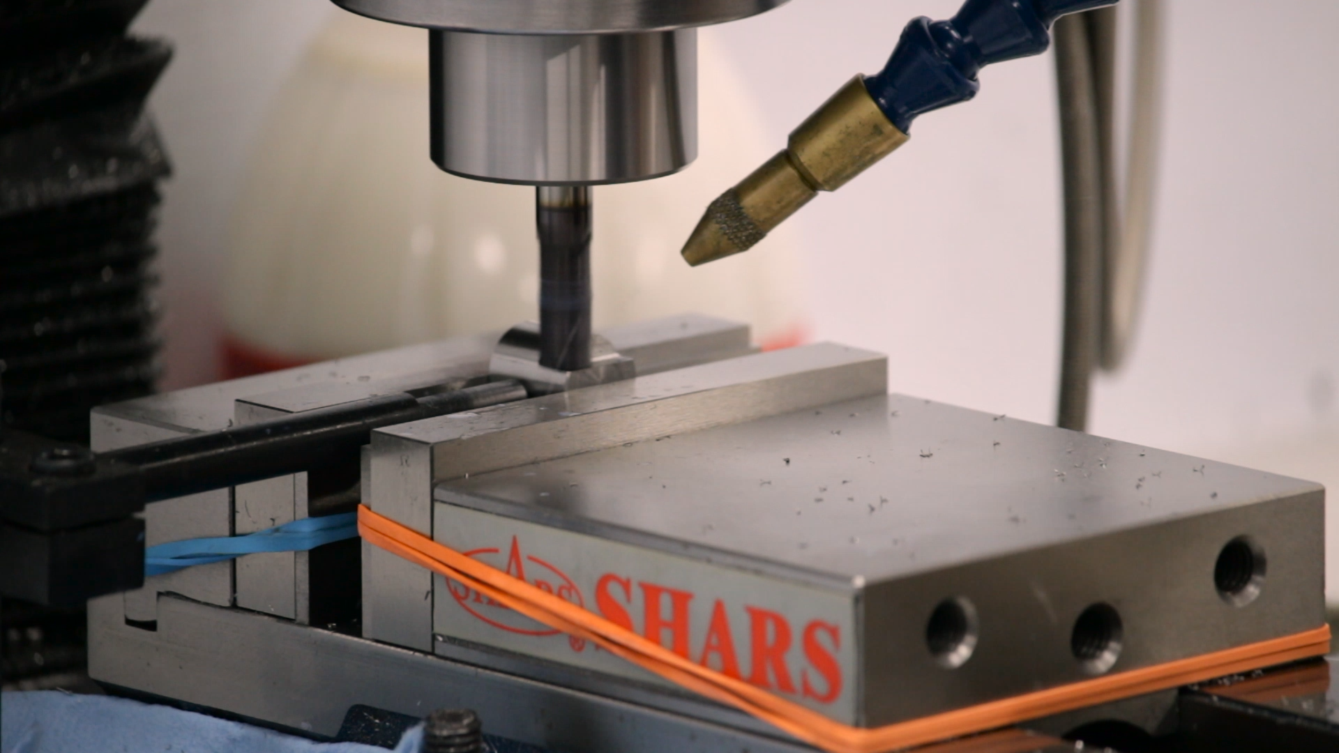
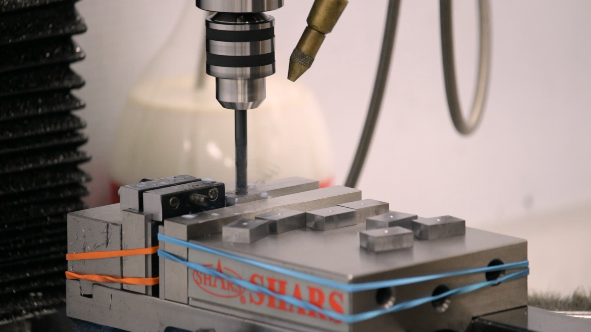
Drilling and Countersinking
Drilling and countersinking the grippers for the mounting screws was straightforward. I used an edge finder to locate both sides and both ends of the blank and used the 1/2 function of my DRO to locate the center. I then spot drilled, drilled and countersunk the holes. I learned a few things along the way, though:
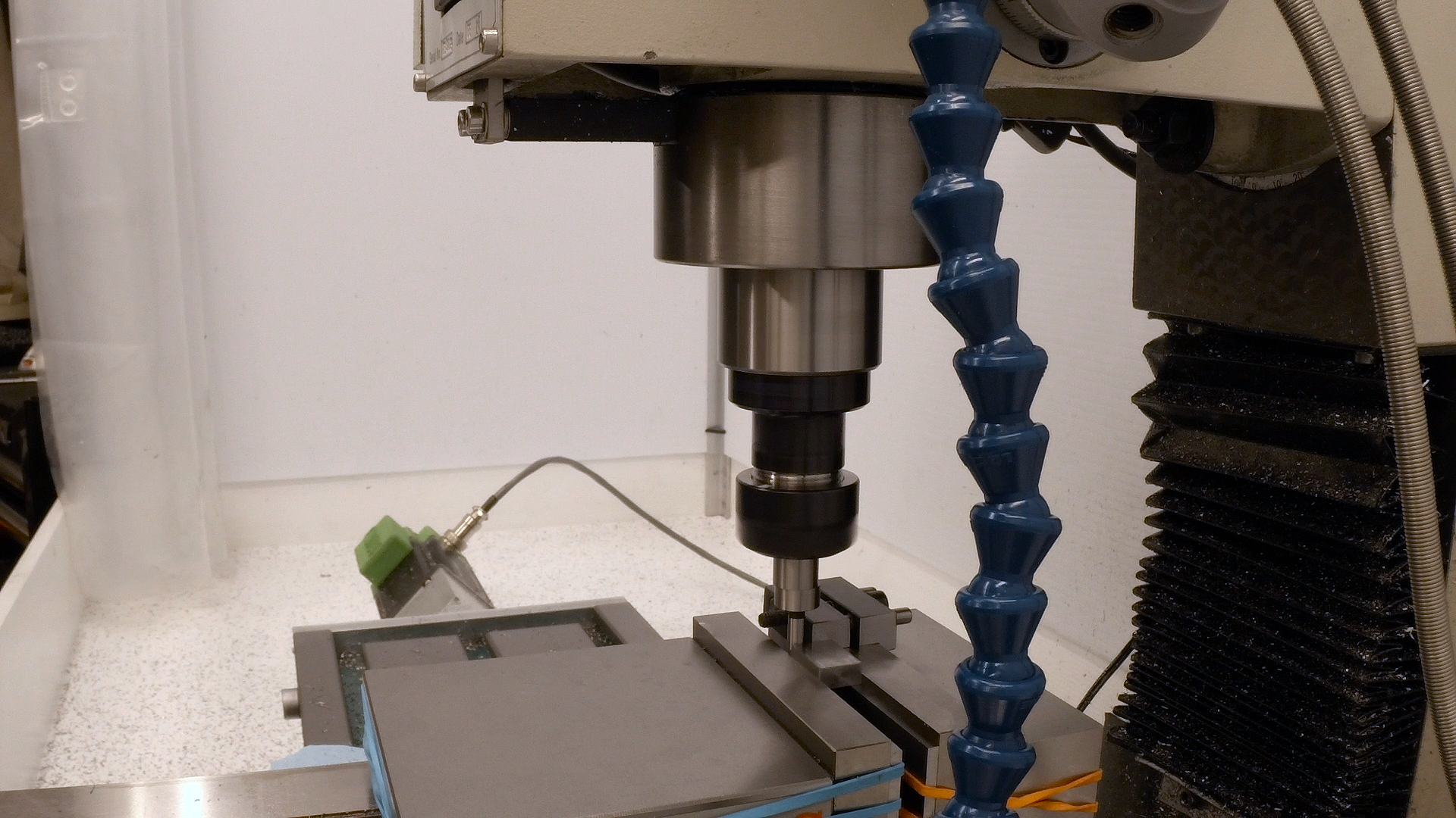
First, the quill in my mill moves when it’s unlocked. I centered up with the DRO on the part before drilling, but to my surprise, the first hole was .005″ off-center. I adjusted it and finished the other seven parts, but later when milled some other features, they were .005″ off-center in the other direction. I adjusted again and it seemed to hold. It took a whole day of head-scratching and I woke up the next morning realizing what must have happened.
I had centered on the part with the quill locked, then unlocked to drill and re-locked to mill again. I went out the shop in the morning, chucked up a drill blank and put a dial indicator on it. When I unlocked the quill, nothing happened at first, but when I pumped it up and down a few times, it floated forward about .005″. When I re-tightened the lock, it went back to its original position.
Note to self: it’s probably best to just CNC spot the holes with the quill locked, and maybe even just do all the drilling with the feeds instead of the quill.
The second thing I learned is that big countersinks needs to run very slowly in my mill. I actually used a 1/2″ 90 degree spotting drill, so it’s probably more prone to chattering than a single-flute countersink. 100RPM gives a very nice hole finish. Anything faster chatters.
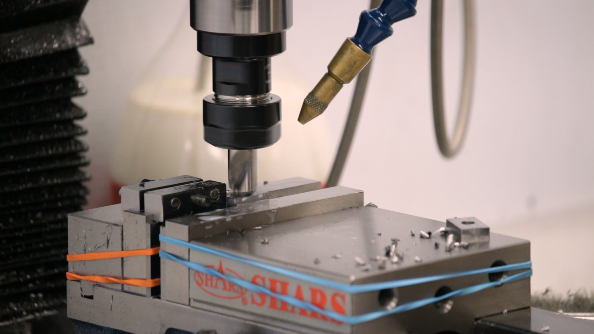
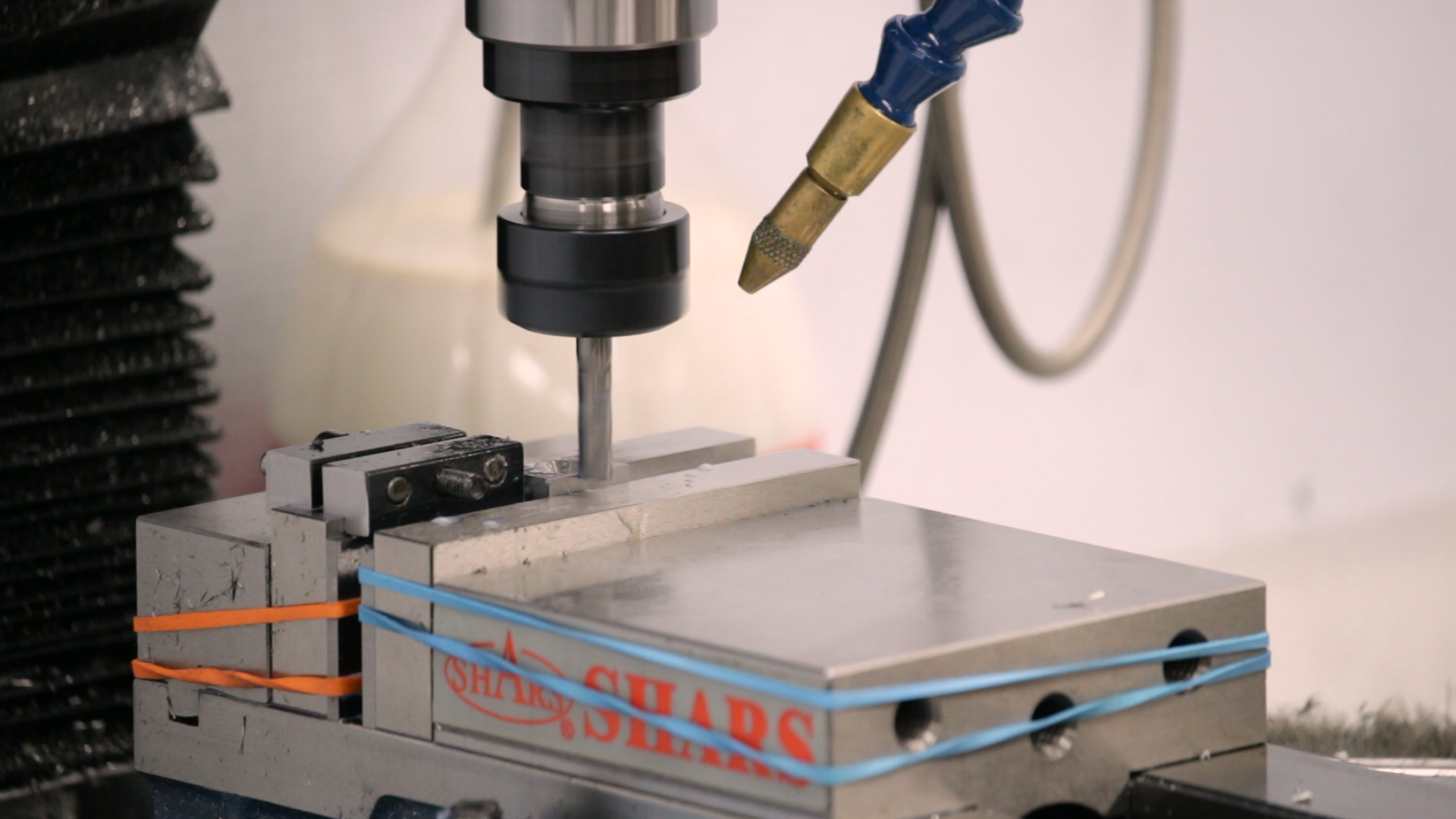
Cutting the Flutes
While I had the mill set up and zeroed with a stop in the vise, I went ahead and cut the flutes in the sides that separate the two teeth. It’s a simple CNC operation to relieve a little material from the side, .019″ wide and .035″ deep. It was at this point that I realized how tiny the features on these parts really are. It’s going to be interesting to see how these turn out once the grooves are in and the teeth are faceted.
Stay Tuned
That’s as far as we got today. Next time we’ll make a fixture to hold the parts at a 45 degree angle in the mill vise to cut the grooves under the teeth.
If you’d like to follow along, here are some of the tools used in this video:
*This site contains affiliate links for which I may be compensated
- YG-1 Tank-Power 3/8″ powdered metal roughing end mill (eBay*): https://goo.gl/4QmiZi
- YG-1 4-Flute Carbide 1/4″ end mill (eBay*): https://goo.gl/1dLomn
- YG-1 1/4″ 120 degree spotting drill (eBay*): https://goo.gl/6zqTzb
- YG-1 1/2″ 90 degree spotting drill (eBay*): https://goo.gl/CpoZ31
Wow. This totally looks like I’m trying to sell YG-1 tools. I don’t know what to say except that I decided to try them after seeing them mentioned by Tom Lipton, and I’m a convert. I’ll keep buying them until I find something better.