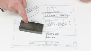
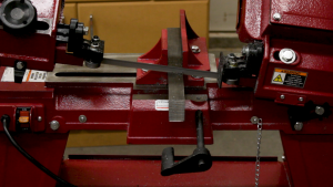
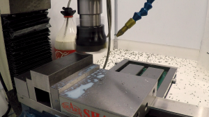
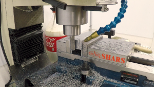
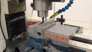
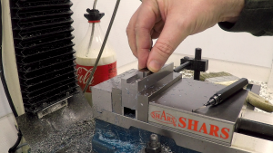
This week, we make the steel vise jaws to hold the grippers we finished last week. We cut and square up the steel blanks and precisely mill the slot. We measure the slot with gauge blocks and check to be sure the steel hasn’t warped from released stress.
The Plan
The vise jaws have a slot milled in the top with a row of threaded holes to accept the grippers. The slot needs to be machined very precisely so the clamping loads are evenly taken up by the walls of the slot and not the screws that hold the jaws in place. The screws position and hold the grippers down, but the jaws need to do the clamping.
Squaring the Stock
The jaws are made from low-carbon cold-finished steel. This presents a little bit of a problem because cold-finished steel has a lot of stress built up in the surface. This means that it tends to move when you mill this material away. One thing we can do to try to minimize this is to take equal amounts off of all four sides of the bar. We do this with a carbide face mill, leaving the blank a little oversize in case it warps and we have to come back and clean it up later. A 4-flute HSS end mill squares up the ends.
Roughing the Slot
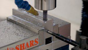
We rough out the slot for the grippers using a powdered metal fine-pitch roughing end mill. This end mill worked great cutting the W1 steel of the grippers and it works great roughing out this slot. I’m really impressed with how well it works in this lightweight (~300lbs) mill. I did some experimenting in Fusion 360, trying to figure out the fastest way to remove the material. Using a high-speed machining (HSM) toolpath with the 3/8″ rougher won hands-down.
Checking for Warping
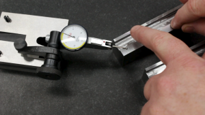
If the steel was going to move due to released stress, it was going to be when we roughed out the slot, so I took the roughed blanks over to the surface plate and checked for warping using a surface gauge and a dial indicator. It turns out that the material moved very little–perhaps a couple of ten-thousandths of an inch. For reference, Mitee-Bite specifies their TalonGrip jaws to be accurate to within 0.002″, which is ten times this much.
Finishing the Slot
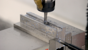
With the parts roughed out and still straight, I switched to a 1/4″ carbide end mill to finish out the slot, measuring as I went using gauge blocks. We know from last time that the grippers are about 0.50025″, so we’re looking for a slot width between 0.5005″ and 0.5010″. The initial cut left us about three thousandths shy of the target, and a spring pass got us closer, but still came up a little short. Adjusting the GCODE to take another .0005″ off each side left us right at .5005″, which fits the grippers perfectly.
Looking Ahead
With the blocks milled to size and square and the slot milled out to the correct width, we just need to drill and tap the screw holes and drill and counterbore the mounting holes for the jaws. We’ll do that next week.
If you’d like to follow along with the build, here are links to some of the tools used in this video:
*This site contains affiliate links for which I may be compensated
- 2.5″ Carbide Face Mill (Amazon*): http://amzn.to/2Bo1VXk
- YG-1 Tank-Power 3/8″ powdered metal roughing end mill (eBay*): https://goo.gl/4QmiZi
- YG-1 4-Flute Carbide 1/4″ end mill (eBay*): https://goo.gl/1dLomn


