Today we’re starting the motor clamp for the toolpost grinder. Now that we have the soft jaws and TalonGrip jaws done, we’re going to put them to good use.
Using the TalonGrip Jaws
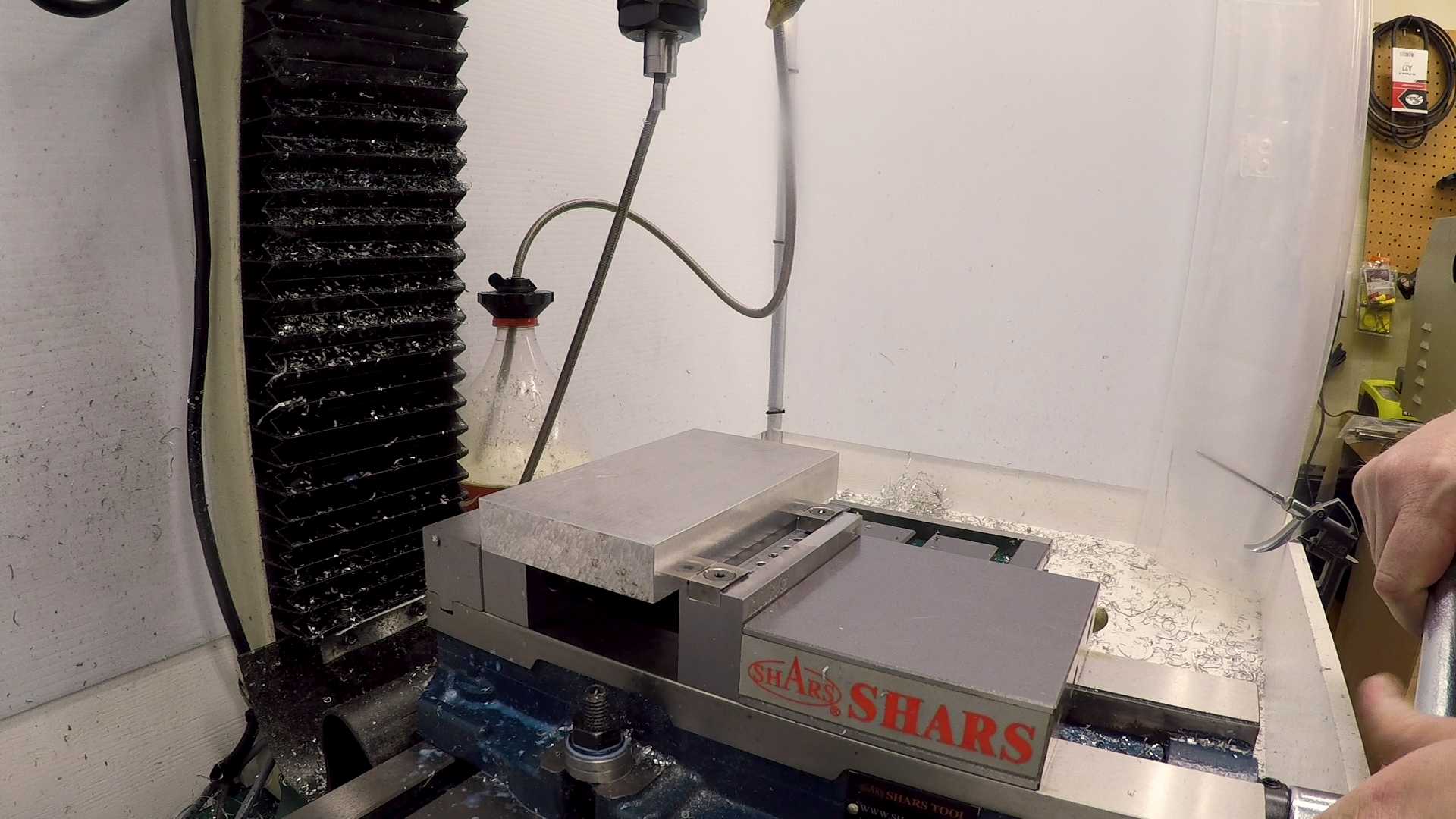
We recently made a set of shop-made TalonGrip vise jaws. These jaws enable us to grab a piece of material in the mill vise by the very bottom edge. Since the jaws only stick up 0.060″ from the bottom of the part, we can machine the entire top side, including the entire perimeter in a single setup. This is perfect for the motor clamp, since it doesn’t have parallel sides and no obvious good way to hold it.
Punching Starter Holes
I didn’t want to try to enter the work with a helical ramp or a plunge. It seems no matter what I try, it always chatters and recuts chips. With a light mill like mine, it groans and vibrates. When the machine is unhappy, I’m unhappy.
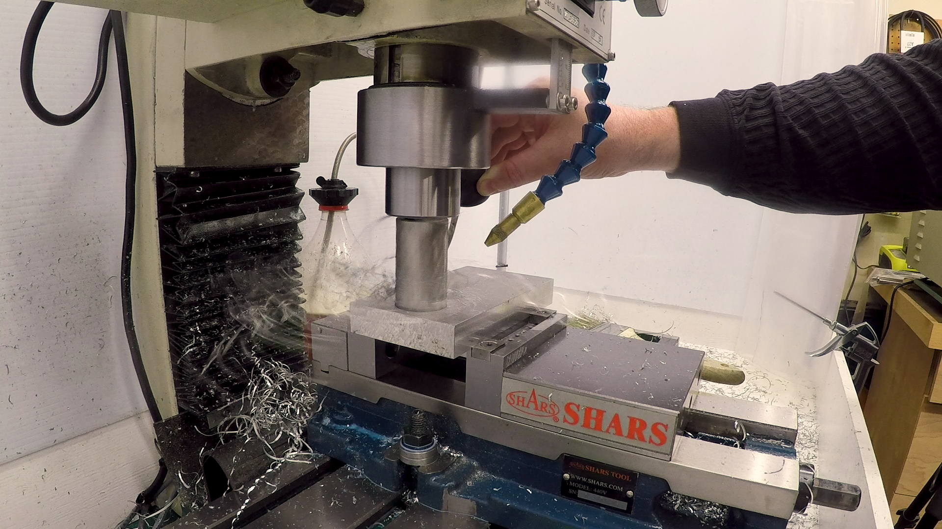
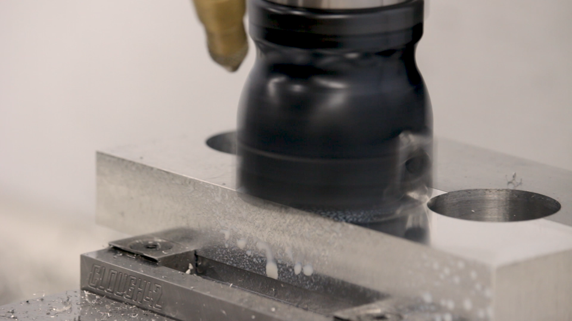
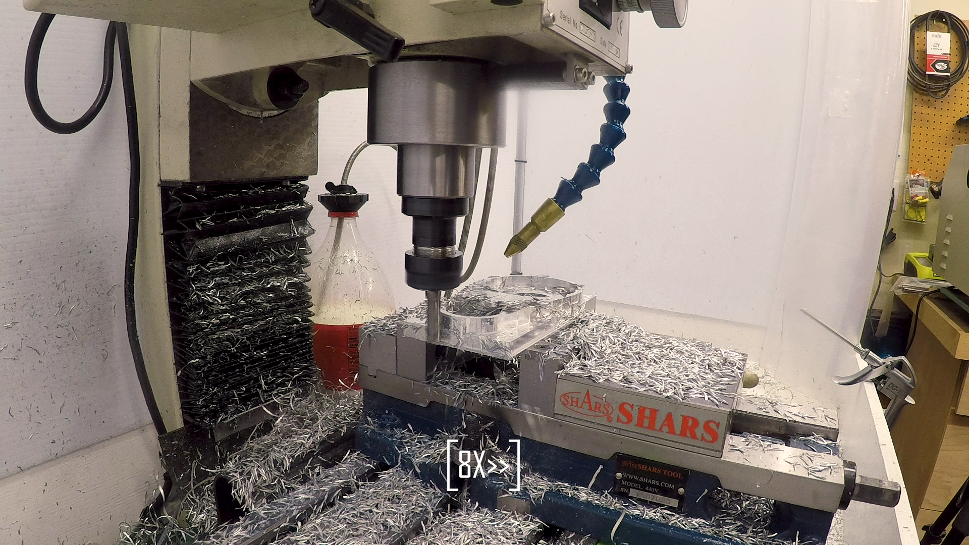
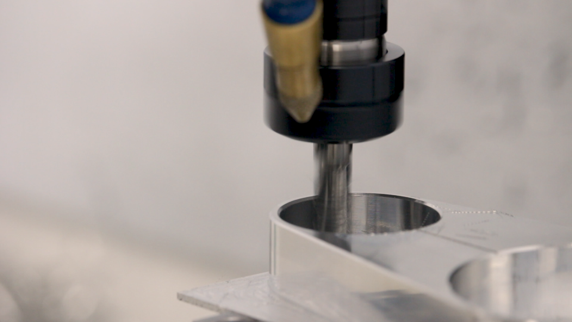
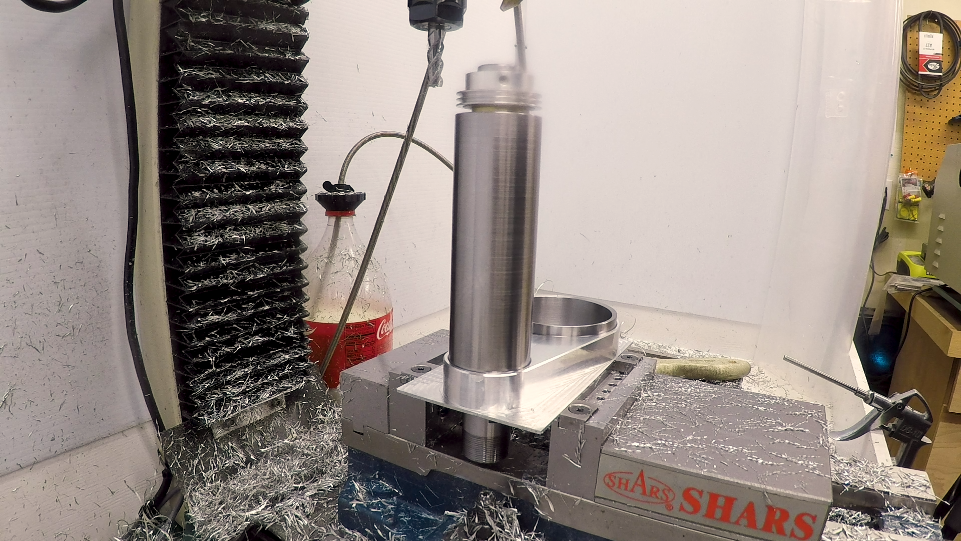
Instead, I decided to try an annular cutter. I used a 1-1/4″ cutter to punch a large hole in the centers of what will eventually become the bores. It cut fast and smooth, though it raised a huge mess of stringy chips. If you watch the video closely, you’ll see that the mill’s speed controller had a hard time with the varying load. Every time I let up to break the chip, it would overspeed, and I’d dig in just about the time it was backing off, causing it to bog. I eventually just left it in the cut and let the chips wind up. The mill has plenty of power, but the brushed DC motor drive couldn’t react fast enough.
Marking the Split Line
I wasn’t really sure how I was going to have to set the part up in the mill later, so I CNC engraved the split line in the surface of the part to use as a reference. We can use this later to align it level in the mill for slitting. I decided to do the engraving before facing, because engraving always raises a burr. By engraving a little deeper than normal and then facing afterwards, the face mill will clean up the burrs.

Facing Off
I love my 50mm face mill. It’s just a cheap offshore face mill, but the polished APKT1604 inserts leave a mirror finish on aluminum–especially with a little soluble oil.
As I had hoped, the face mill cleaned up the engraving and left a nice, sharp line with no burrs.
Milling the Part
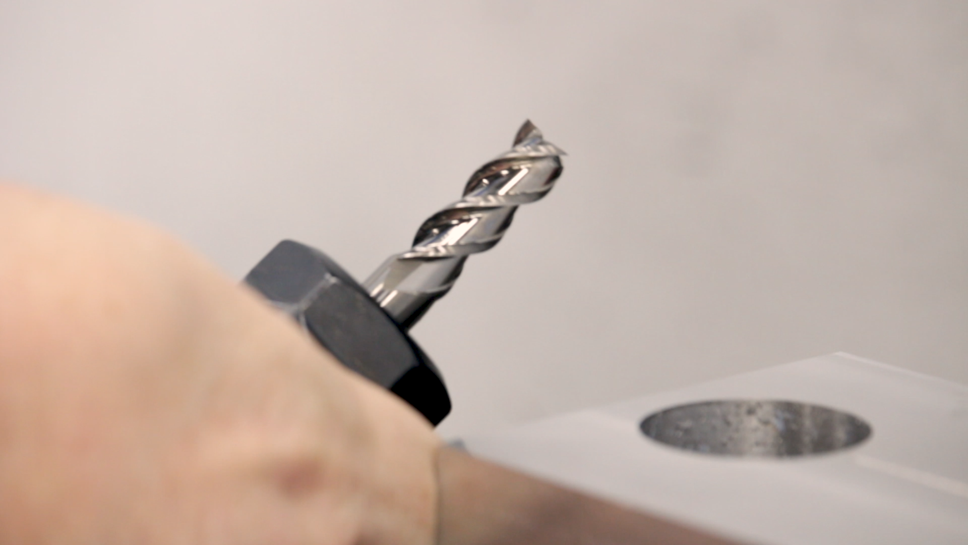
There was a lot of material still to remove, so I used a 3/8″ solid carbide aluminum-specific end mill. This one is a YG-1 Alu-Power. I’ve used the 1/4″ Alu-Power end mills for a while now, and I love them. The 3/8″ is probably the largest I really want to run in this mill. If I push it hard, it can set up a pretty good vibration in the mill.
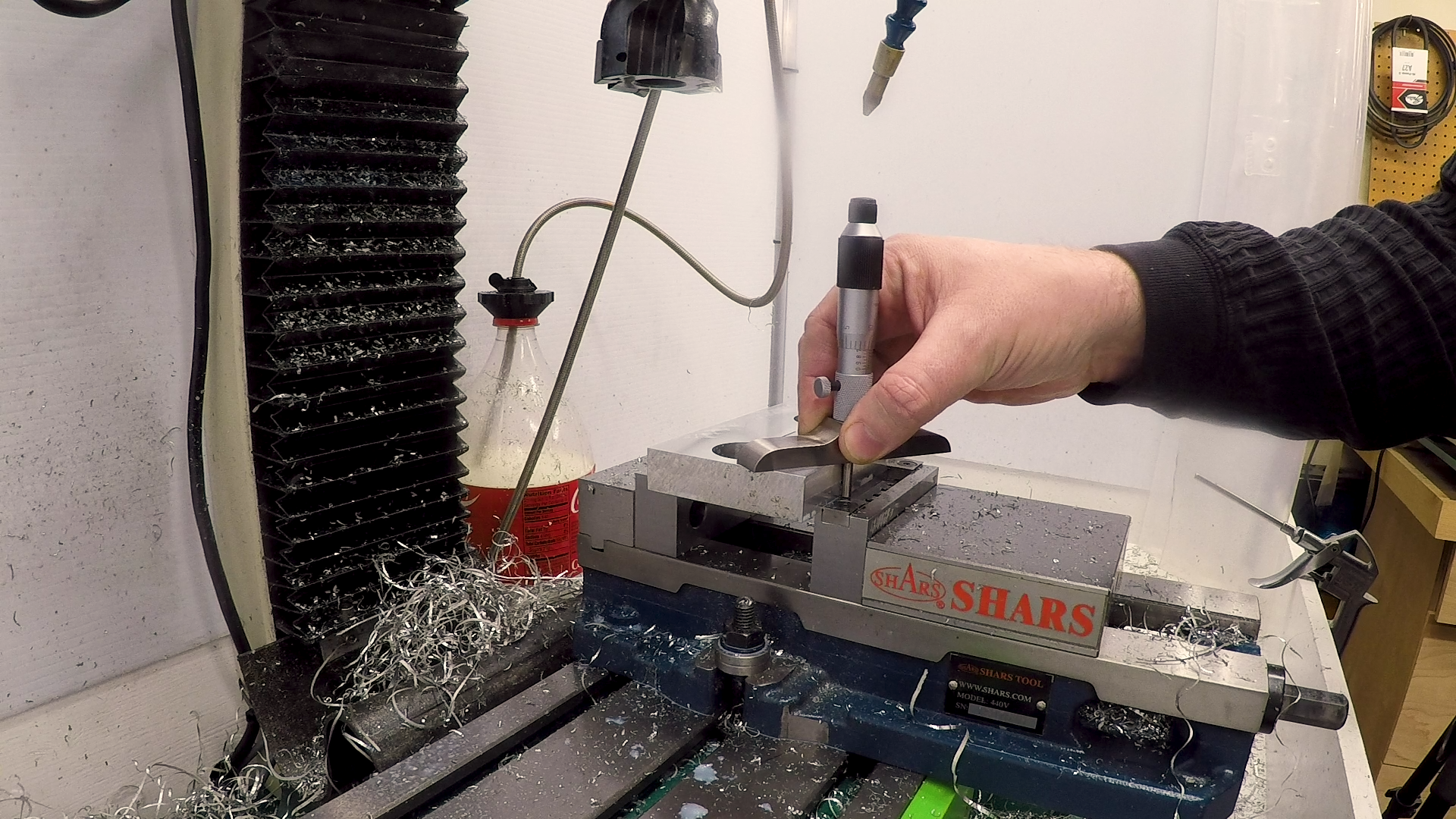
Given that I’m planning to mill down to a waterline just 0.010″ above the hardened TalonGrip jaws, I checked with a depth micrometer first to make sure they would clear.
The end mill plowed out the material, and made large drifts of aluminum snow in the enclosure.
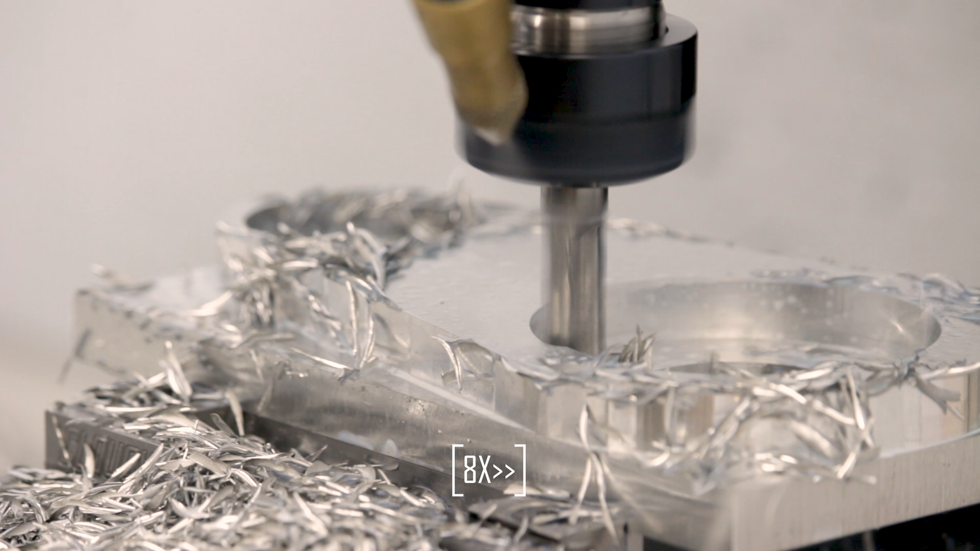
I took the material with an adaptive clearing HSM toolpath in two depths of up to 3/8″ (one tool diameter). The last pass was a .020″ contour at full depth to clean up the sides. It left a mirror finish. A chamfer cleaned up the edges.
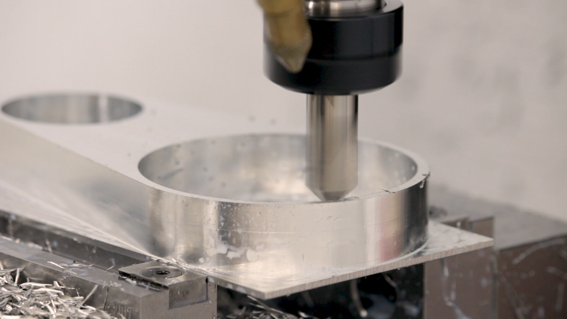
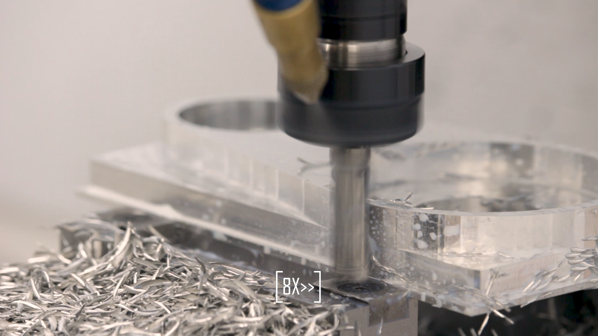
Fitting the Parts
This clamp has to fit around the motor eccentric and the spindle, so the bores need to be right on-size. After the first contouring pass, both bores were too small. I ran a couple of spring passes with the same dimensions, and the motor bore cleaned up to size. This is pretty typical with a small machine tool like this. There’s a lot of flex in the frame of the machine, and it takes a couple of spring passes to reduce the tool pressure and come completely to size.
The spindle is actually about .0005″ oversize, so I had to take a little extra out of the spindle bore. I just told the CAM to leave negative .0005″ of material on the wall and ran the contour again.
Up Next
That’s it for today. Next time, we’ll make a set of soft jaws and machine the other side.
If you’re following along with the build, here are links to some of the tools used in the video:
*This site contains affiliate links for which I may be compensated
- Steel Dragon 1-1/4″ x 2″ HSS Annular Cutter (Amazon*): http://amzn.to/2BluZ4y
- 50MM Face Mill with APKT inserts (eBay*): https://goo.gl/npAADu
- YG-1 3/8″ Alu-Power end mill (eBay*): https://goo.gl/g6Kpp7
- YG-1 1/2″ 90 degree spotting drill (eBay*): https://goo.gl/CpoZ31