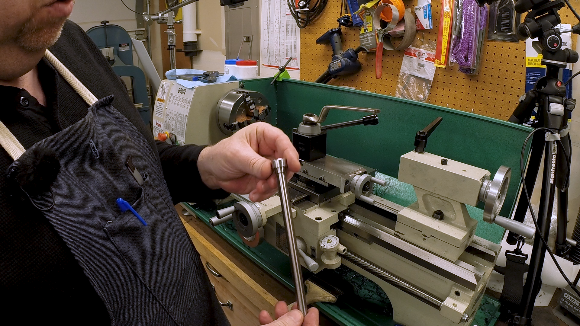
This week we’re finishing the drawbar for the toolpost grinder. Last week, we turned the body of the drawbar and formed the head. Now we need to turn down the end, single-point the threads and finally take it over to the mill to put on the wrench flats.
Forming the Diameter
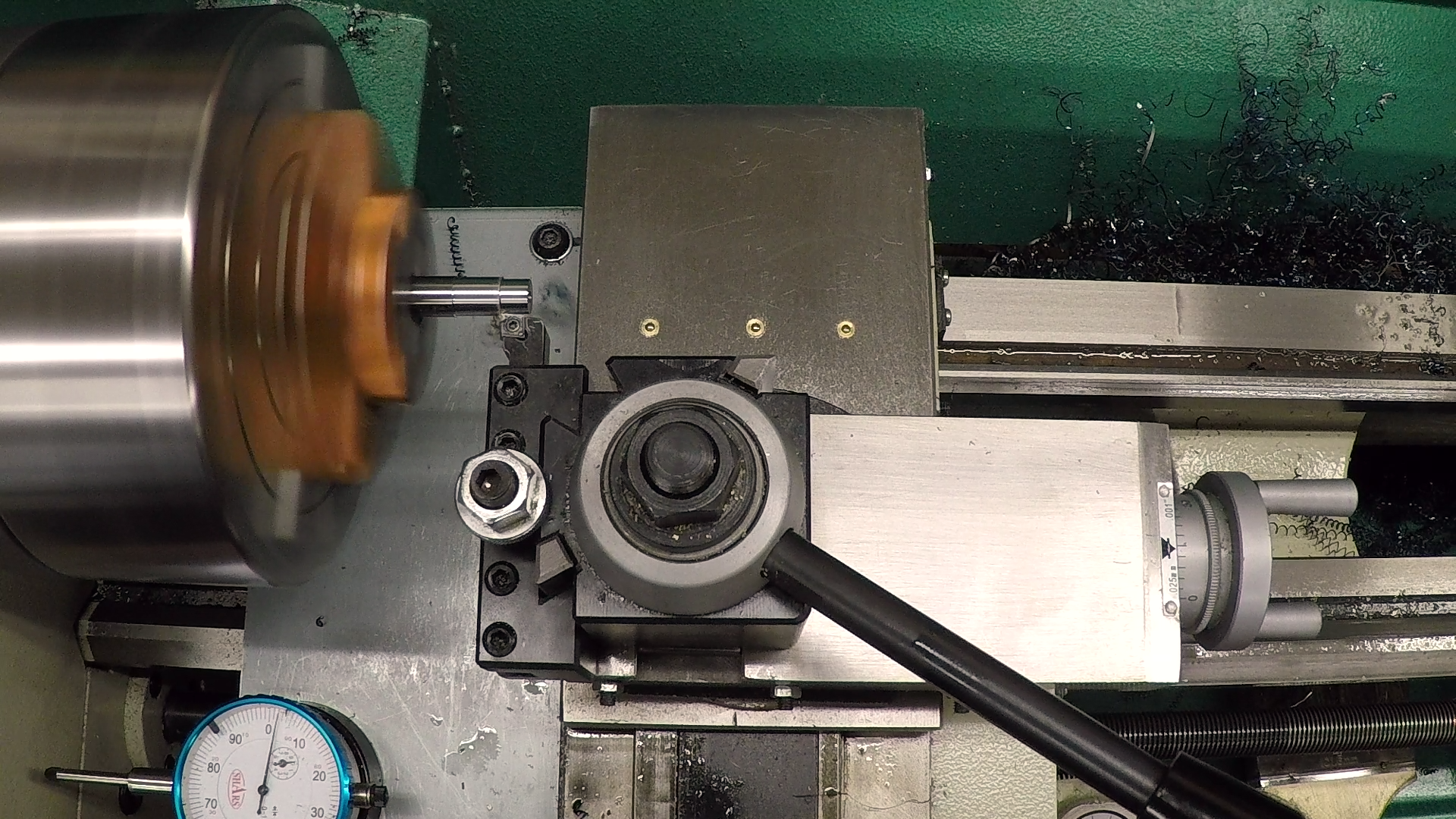
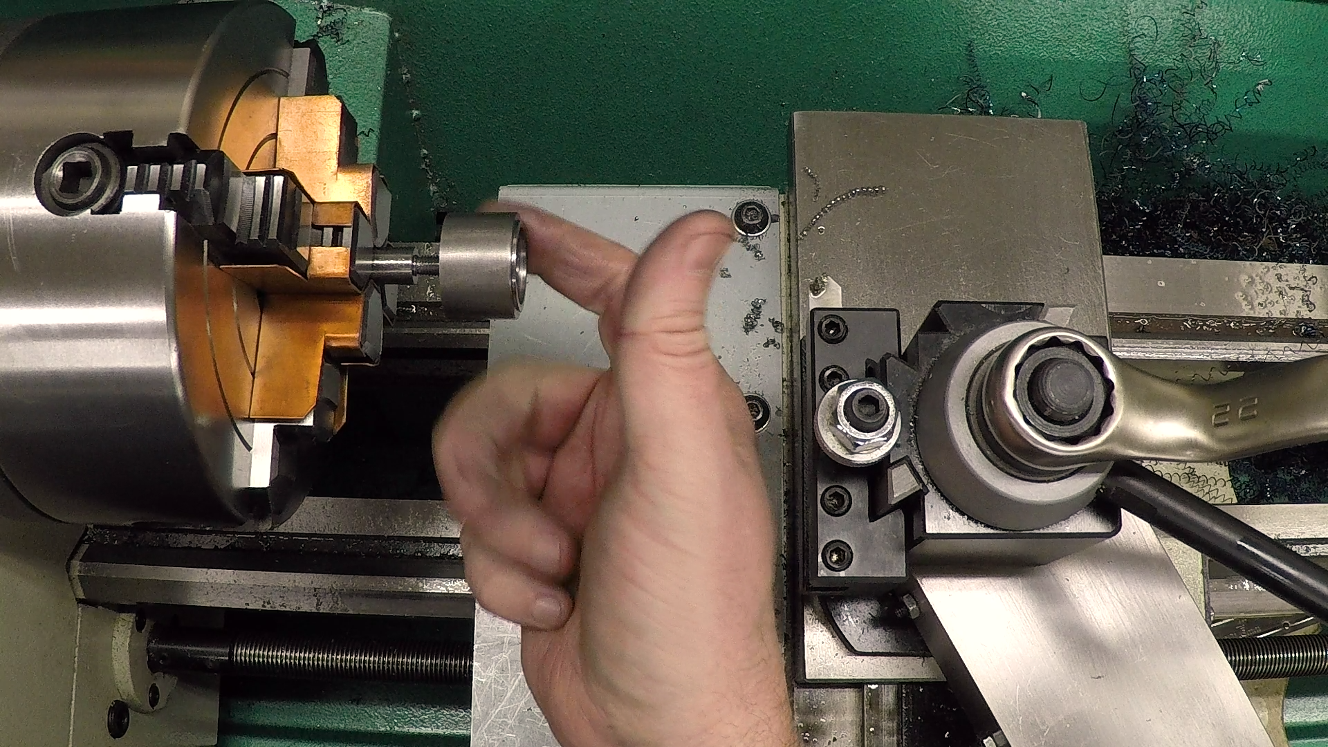
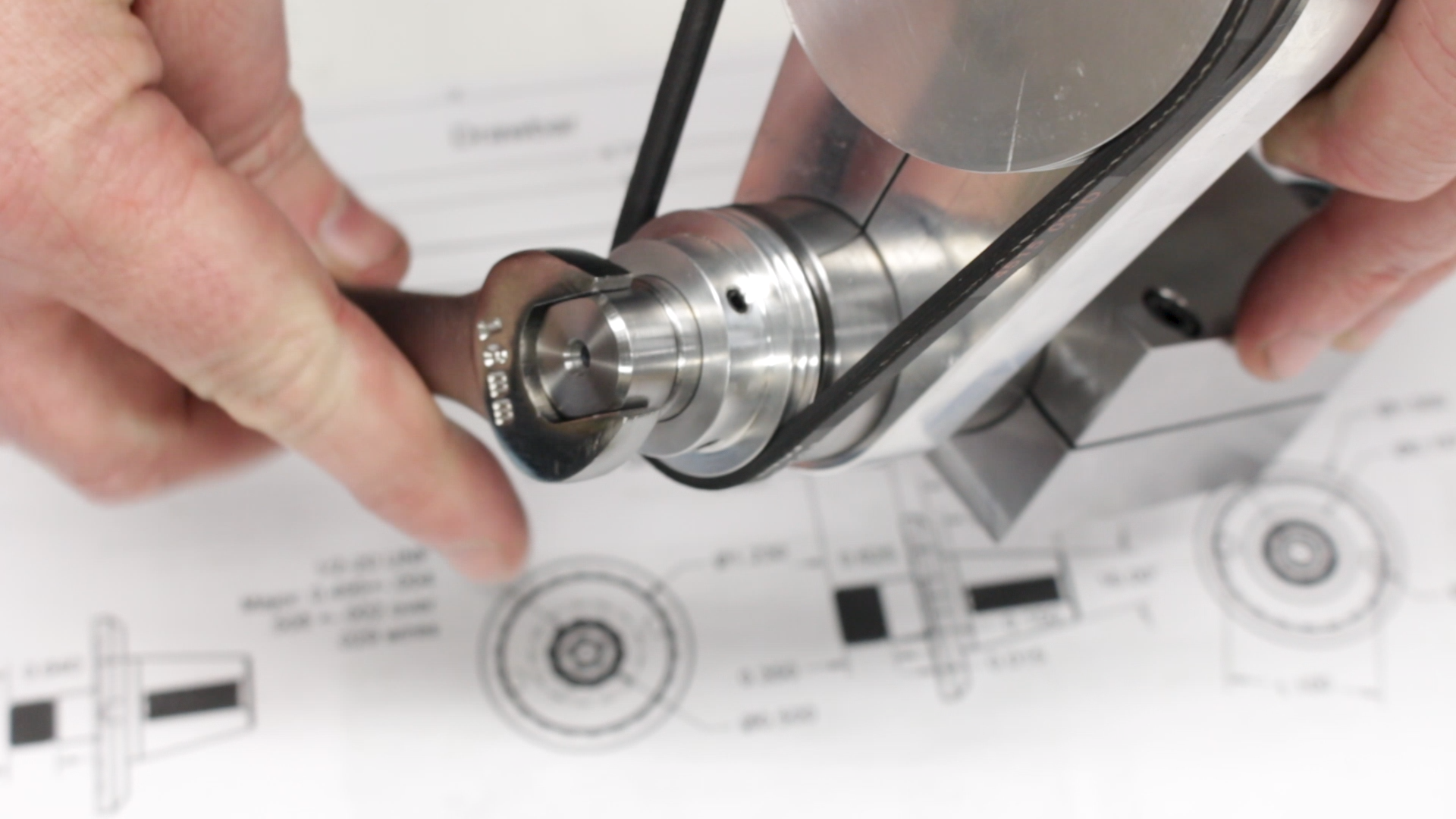
Starting with the blank we made last week, the first step was to flip it around in the 4-jaw chuck and get it indicated. I decided not to try to use a center for a couple of reasons. First, I didn’t think it was needed with the short stickout, and second, it would seriously have been in the way. It’s possible to get the turning tool in next to the center, but the threading tool is a much bigger challenge. And even if I could get it in there, I would have zero margin for error. If I missed my mark on the thread dial, there would be no time to un-clamp and try again before the part was destroyed.

Threading
Have I ever mentioned how much I hate change gears? I usually do whatever I can to avoid single-pointing threads, just because I hate changing the gears on my lathe. It takes 10-20 minutes to get everything switched over and the backlash set. And in the process, I usually skin a couple of knuckles. For some reason I don’t understand, one of the shafts has a cap screw, the second has a one-piece milled lock and the third uses an e-clip. Who designed this thing?
I decided it was worth the trouble this time because I wanted to fit the threads exactly to the arbors (or rather to the tap I’m going to use to make the arbors). The reason for this is because the threads on the drawbar are the feature that centers the drawbar in the spindle bore. I want it to spin as centrally as possible to avoid vibration, so I single-pointed the threads.
Since I’m threading up to a hard shoulder, I first cut a relief for the thread tool so I have someplace to stop without having to quick-draw to avoid the shoulder.
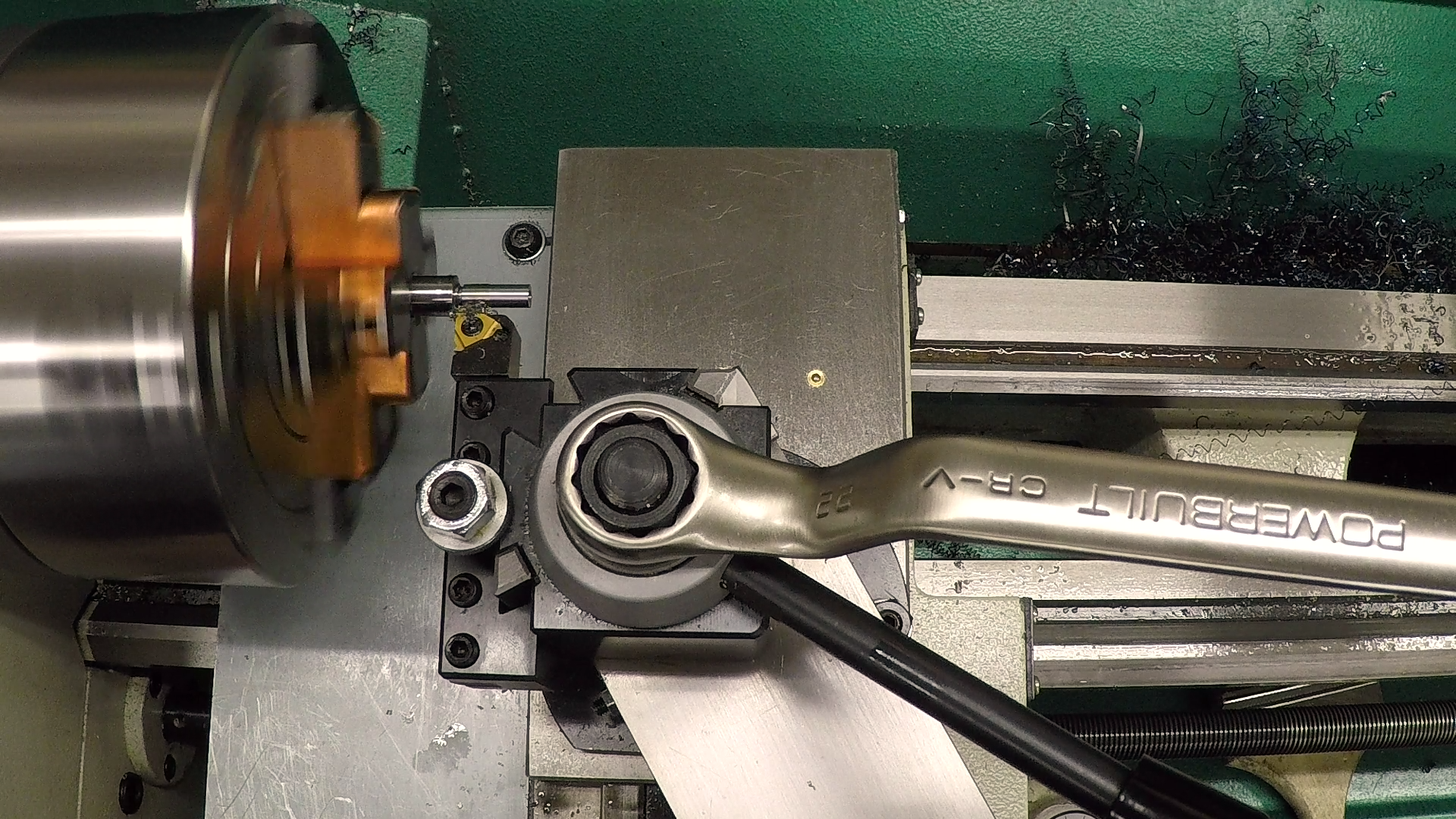
The threading went relatively well, given the difficult material. It might have been better with a more rigid lathe, but with my lathe, it was a challenge. The threads ended up looking pretty good to the naked eye, but under magnification, you can see that there is some tearing on the front face of the threads. The back face that actually engages the arbor is smooth enough.

After threading, I cleaned up the peaks with a triangular file, first tipping it one way and then the other to round over the peaks.
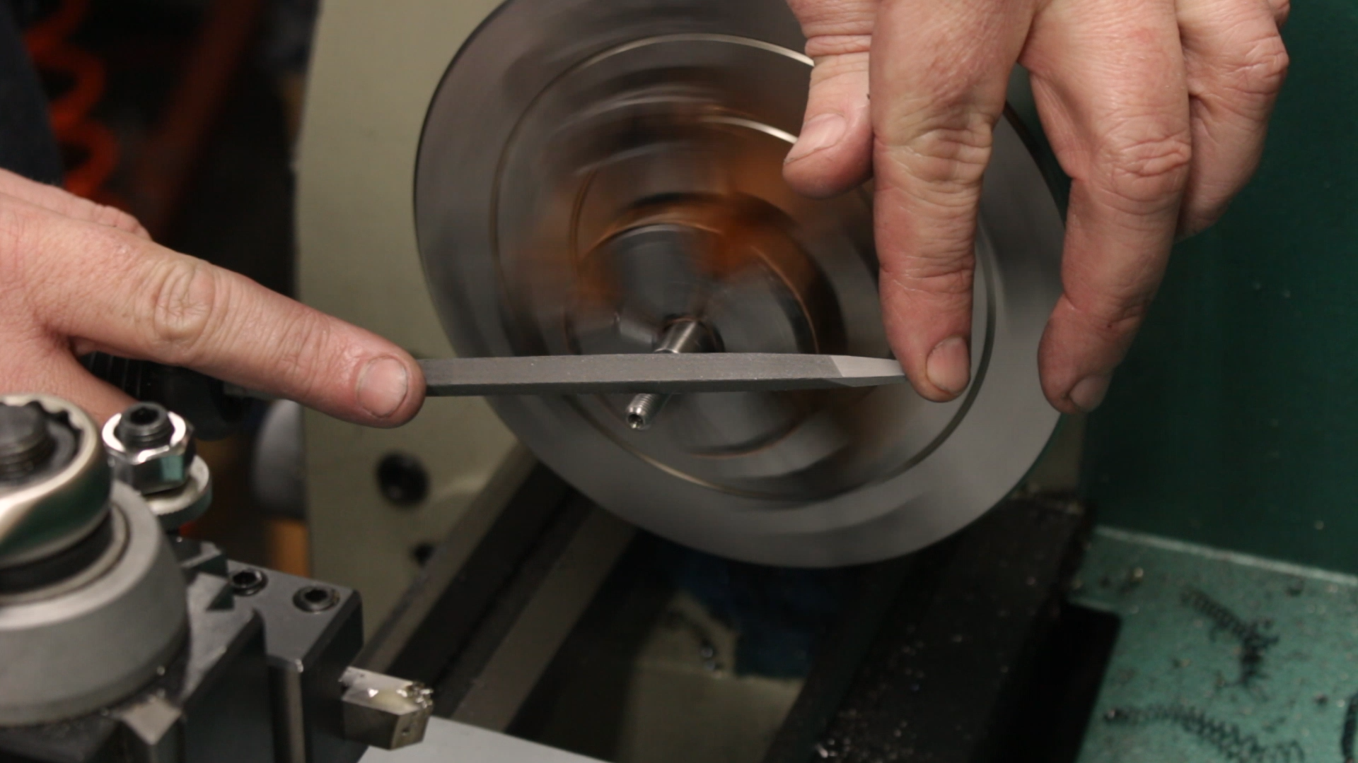
As I went, I repeatedly tested the threads with a test part that I made earlier. This is just a piece of 1018 steel, drilled and tapped with the same drill and tap I’ll be using when I make the arbors. This allowed me to sneak up on a nice, tight, but smooth fit.
Forming the Flats
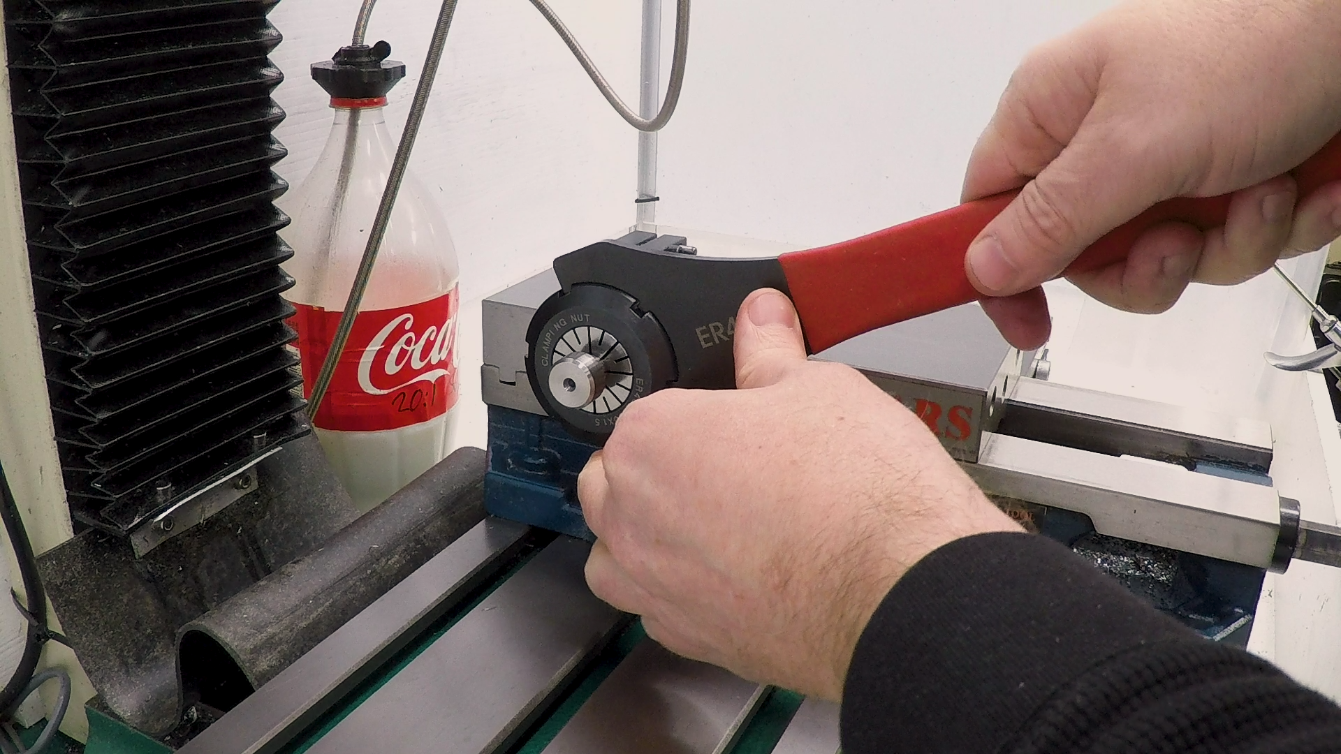
The last step was to take the drawbar to the mill to form the flats. I deliberately chose 7/16″ for the main body diameter because I have a 7/16″ ER40 collet for my square collet block. I mounted the block in the lathe with a stop so it would be easy to flip it over and mill both sides of the drawbar without losing my zero.
I didn’t bother with an edge finger because the flats just don’t need to be that precise. Instead I brought the carbide end mill down until it touched the surface, then did the same on the face. I cut the flat in a couple of roughing passes followed by a .005″ finishing pass to clean it up on both the bottom and the shoulder.


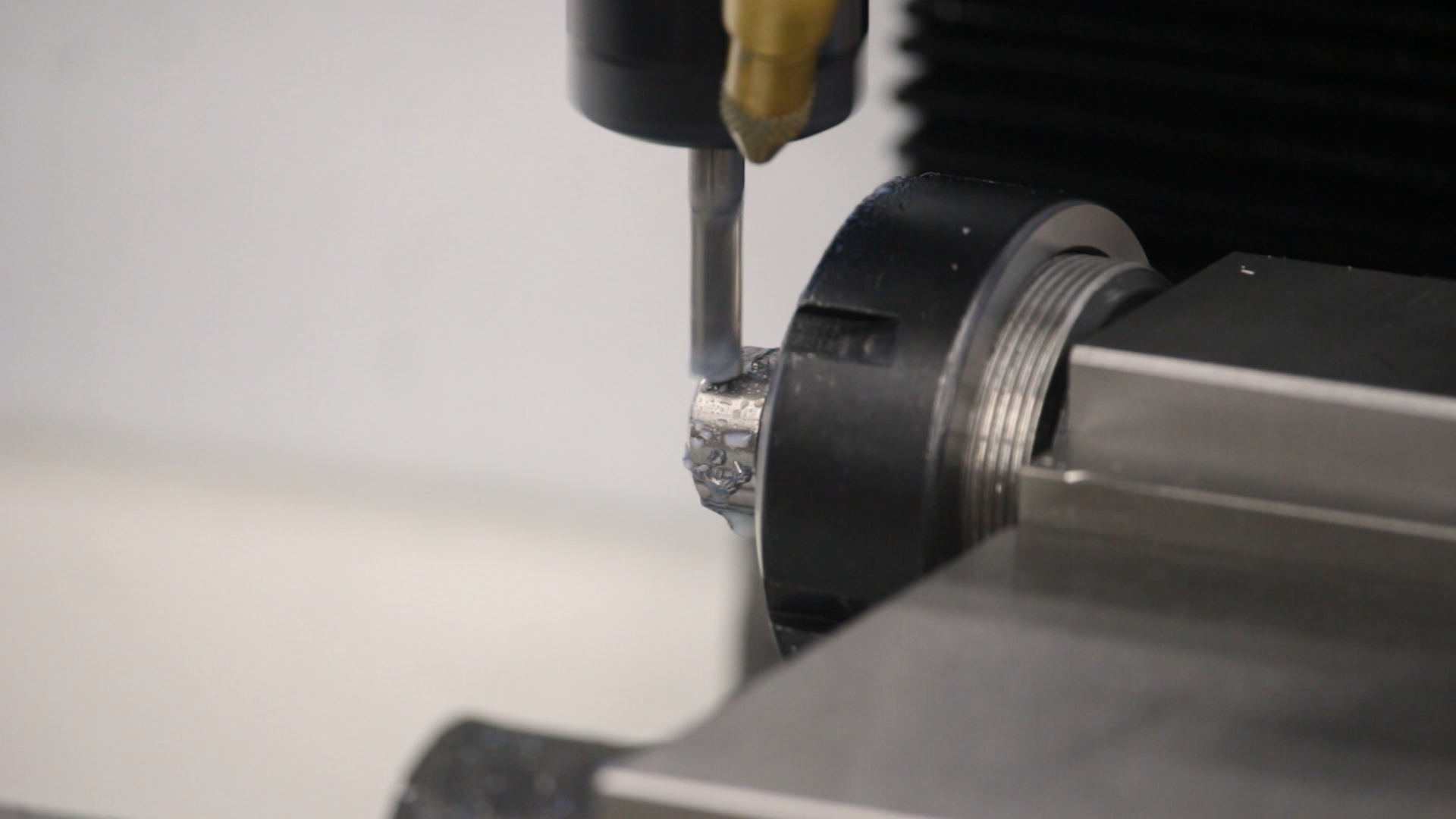
After milling one side, i flipped the collet block, re-registered it against the stop, and milled the other side.

Even with my sloppy method, the dimension across the flats came out pretty close: .0627″. This is 15.94mm. The tolerance for a 16mm fastener head is from 15.73 to 16.00mm.
Putting it All Together
After a little deburring with a file and some Scotch-Brite, I took the finished drawbar over to the bench to put it together.
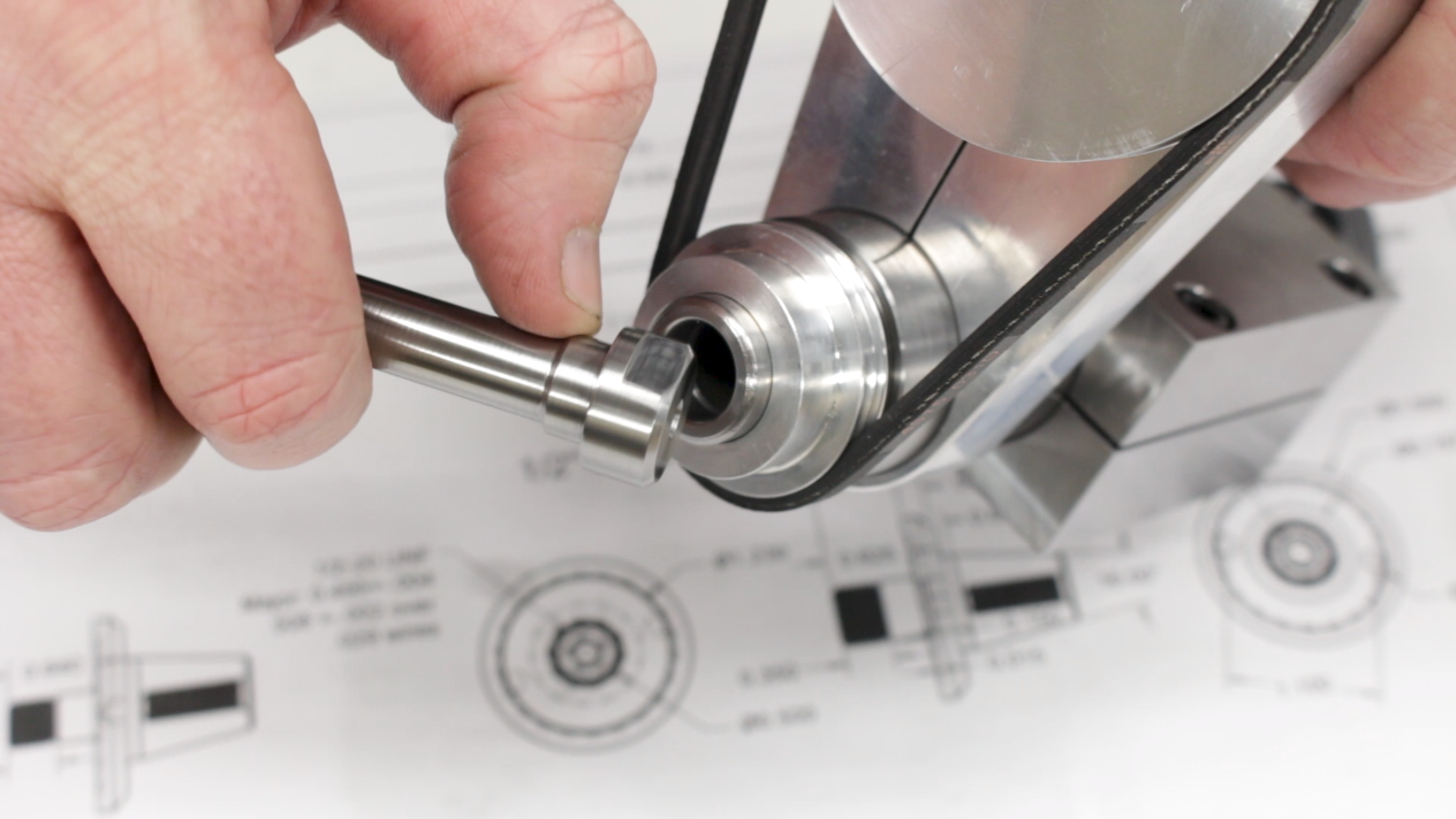
I’m pretty happy with how it turned out, even though it’s technically the third try. The register fits quite well. It turns easily, but has very little play, and the wrench fits easily. I think this is going to work out well.

Next Steps
That’s it for the drawbar. Next, we’ll start on the wheel arbors.
If you’re following along with the build, here are some links to some of the tools used in the video:
*This site contains affiliate links for which I may be compensated
- Shars CCMT0602 RH turning tool holder (eBay*): https://goo.gl/Q1Jsdp
- External carbide threading tool: (eBay*): https://goo.gl/mtD1DV
- iGaging 0-1″ Digital Micrometer (Amazon*): http://amzn.to/2EdYXZq
- ZLiveCenter 3MT triple ball bearing live center (eBay*): https://goo.gl/nE1u2o
- YG-1 4-Flute Carbide 1/4″ end mill (eBay*): https://goo.gl/1dLomn