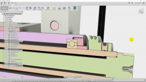
Today, we’re working on the toolpost grinder again. This time, we make the brass spacers.
We need the spacers because the lock rings block direct access to the inner bearing races. Locking the bearings in place like this makes them very stable, but it means that we need a couple of spacers to bridge the gap and carry the axial loads.
Boring a Drawbar Register
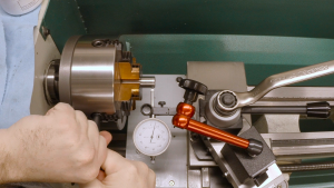
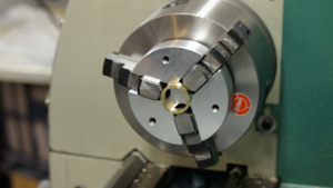
But before we get to the spacers, there’s one other item that needs attention: the collet holder needs a register to eventually accept the drawbar. We don’t have to do this now, but the spindle will soon be assembled, and the 4-jaw chuck is already in the lathe, so this seems like as good a time as any. It’s a simple task. We just need to touch the inside of the bore to true it up and face the end to ensure it’s flat.
The diameter and length of the register don’t matter at all. It just needs to clean up the drilled bore in the collet holder and make it concentric. We will fit the drawbar to it later.
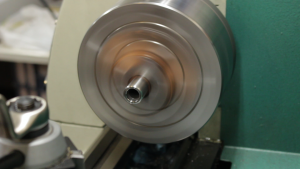
The spacers are cylindrical, so they’re a simple piece of turning. I found a chunk of brass and decided to use it for the color contrast.
Turning the Spacers
All of the dimensions of the spacer are critical. The bore fits over the collet holder body, and we want it to be a close fit. We don’t want the spacers spinning off-center, but they also need to be able to slide freely on the shaft to allow the spring to preload the bearings properly. This is just a matter of using a high-speed steel boring bar and sneaking up on the dimension using a telescoping gauge and a micrometer.
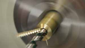
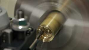
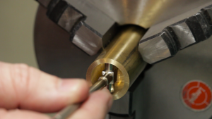
The outside diameter is also important. It doesn’t have to fit anything tightly, but there’s only about a quarter-millimeter of clearance between the outside of the spacer and the inside of the lock ring. Any dimensional problems here could lead to contact, which we definitely don’t want.
Parting and Facing
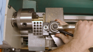
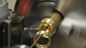
After turning the outside diameter, we need to part off two spacers. Getting the faces parallel is important so the bearing races and the pulley will run true. Of course, holding such a small part in the chuck jaws and getting it to run true is a challenge, so I pulled out lathe spider. The spider is a shop-built backing plate made from 3/4″ aluminum tooling plate and fitted with three set screws to adjust its depth and dial it in to run true. It is machined to fit tightly around the lathe jaws so it will stay in place and spin true.
The Finished Product
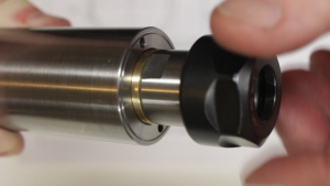
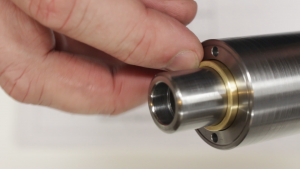
In the end, the spacers fit perfectly, and the yellow brass is a very nice contrast to the steel body of the spindle. Everything fits and spins freely. I especially love the narrow clearance between the spacers and the lock rings. It’s just under .010″ and it looks great. I would probably try to narrow the gap even further if I built it again, but this should be fine.
Next time, I think we’ll start on the pulleys. Once we have the motor pulley done, we can finally lock everything together and preload the bearings. I’m looking forward to that.


