This is just a quick video showing how to CNC mill soft jaws using Fusion 360.
In the previous video, I used soft jaws in the mill to hold the toolpost grinder motor clamp so I could mill the back side. YouTube viewer bostondan77 asked in the comments how I set up the CAM to carve the soft jaws and I realized that I skipped right over that.
This video shows how I did it. Perhaps there are better ways. If so, feel free to comment and let me know.
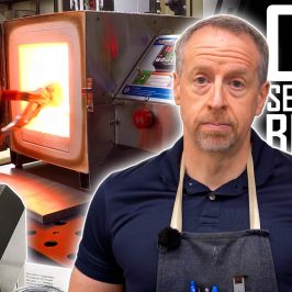
The Part
In case it wasn’t abundantly clear, the reason we needed soft jaws for the motor clamp is because it doesn’t have parallel sides. After milling the basic shape out of a solid block of aluminum, there isn’t a good way to flip it over and hold it in flat vise jaws.
Modeling the Soft Jaws
The goal is to model a set of soft jaws with a recess to accept and firmly grip the milled portion of the part. The first step is to set up models of the jaws in Fusion 360 so we have something to carve. In my case, I already had models of the vise jaws because I made them in a previous video.
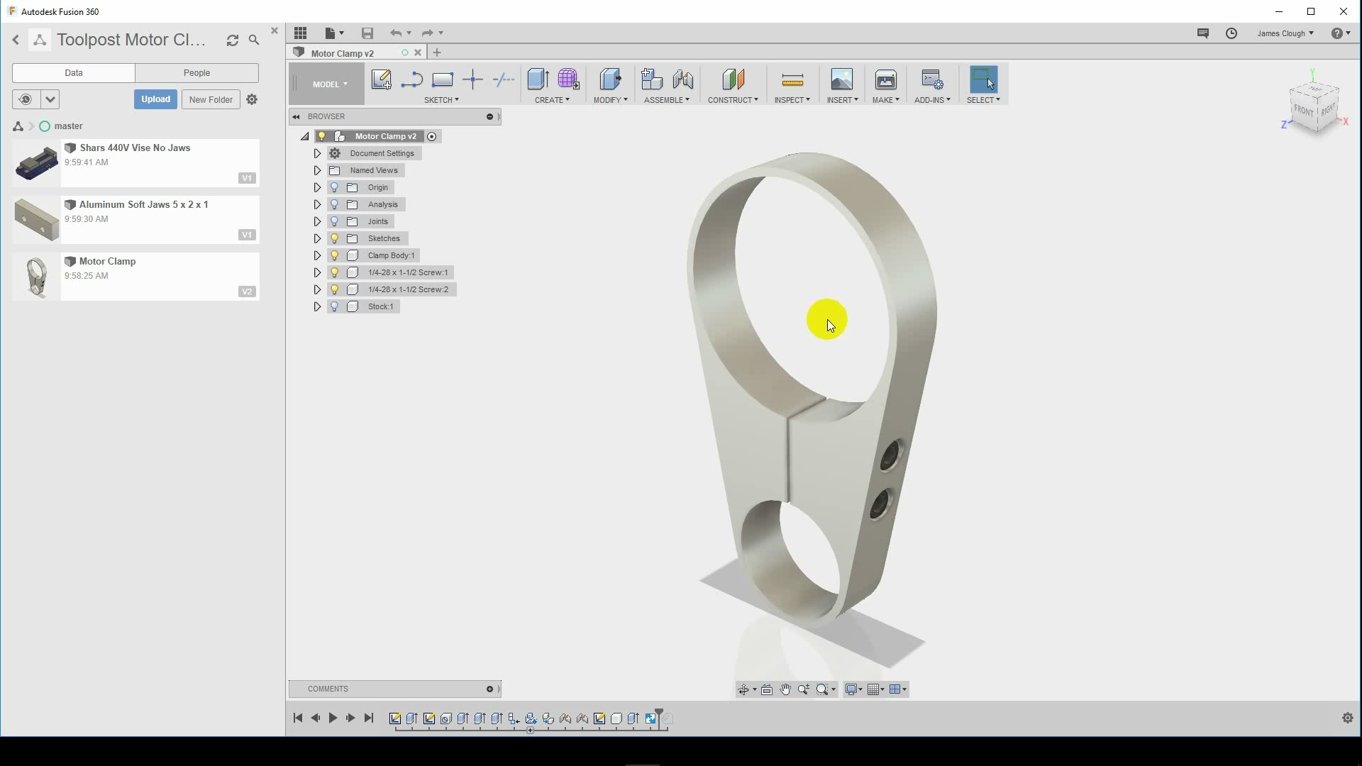
For the CAM workspace, I created a new design and imported the soft jaw models as linked designs. I usually create a new design and mock up the entire setup for the CAM process. Unless it’s a very simple operation, I find this more convenient than trying to do the CAM in the original design. It also keeps setup and fixture elements from finding their way into the drawings.
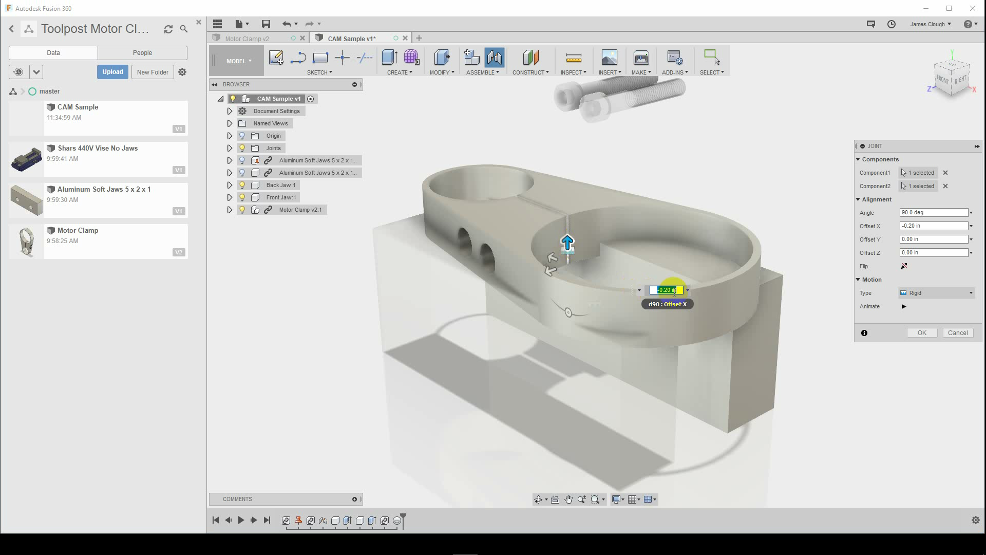
The jaws are joined on their faces with an offset to set the distance between them. I guessed how far apart they needed to be and then adjusted later.
Making Machinable Bodies
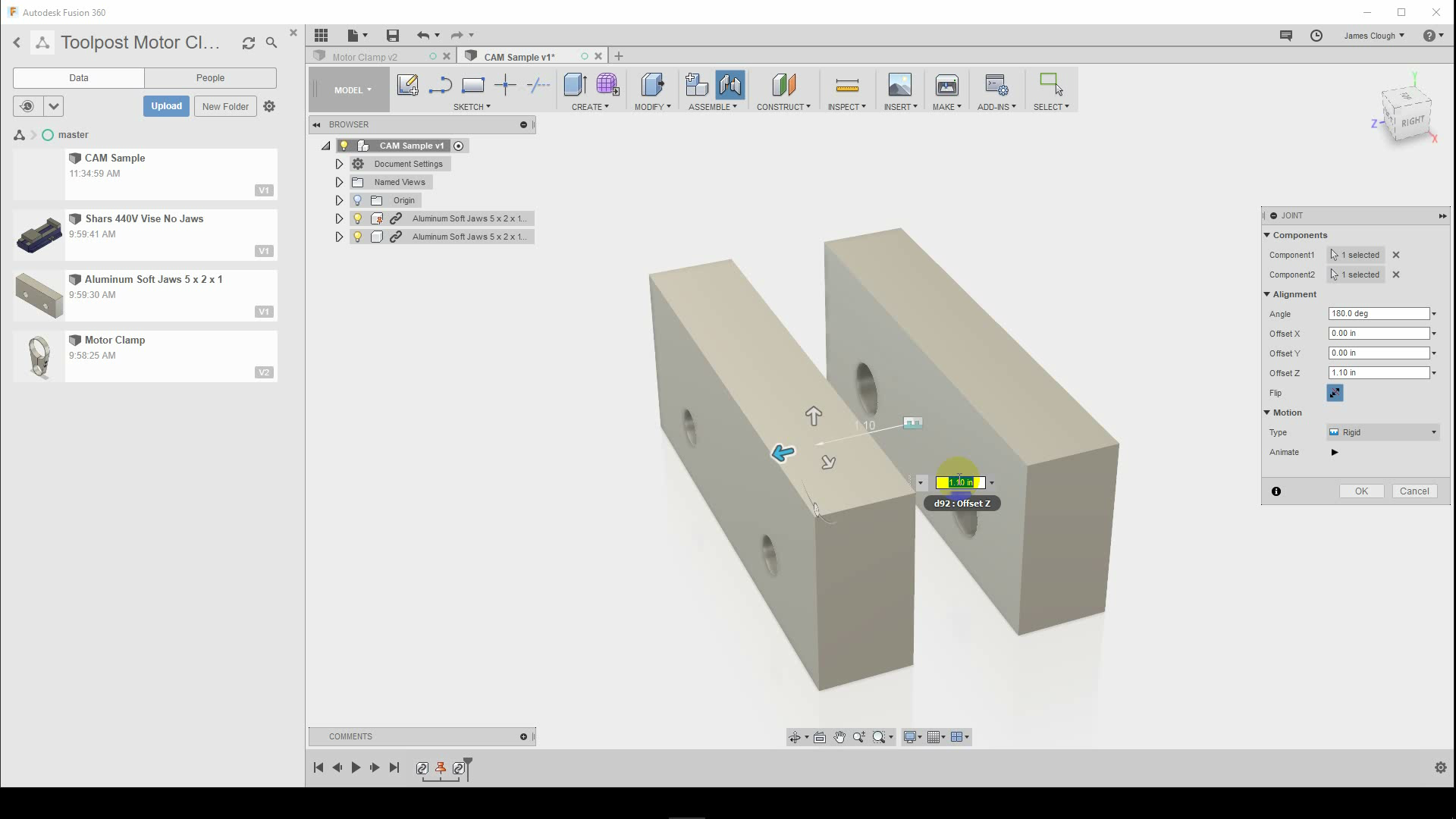
The jaws in this case are linked designs, so I can’t model the cuts directly. Instead, I used the surfaces of the parts to extrude new bodies the same size in the same position. These, I can carve in this design, and the imported models become the stock for the setups.
Positioning the Part
Once I had the jaws in position, I used “between two faces” joints to position the part on top of the jaws, centered between them. I then offset the joint downward by a quarter inch to sink the part into the top of the jaws, the way I wanted it to be held. After positioning the part, I then adjusted the space between the jaws by editing the joint between them.
Modeling the Cuts
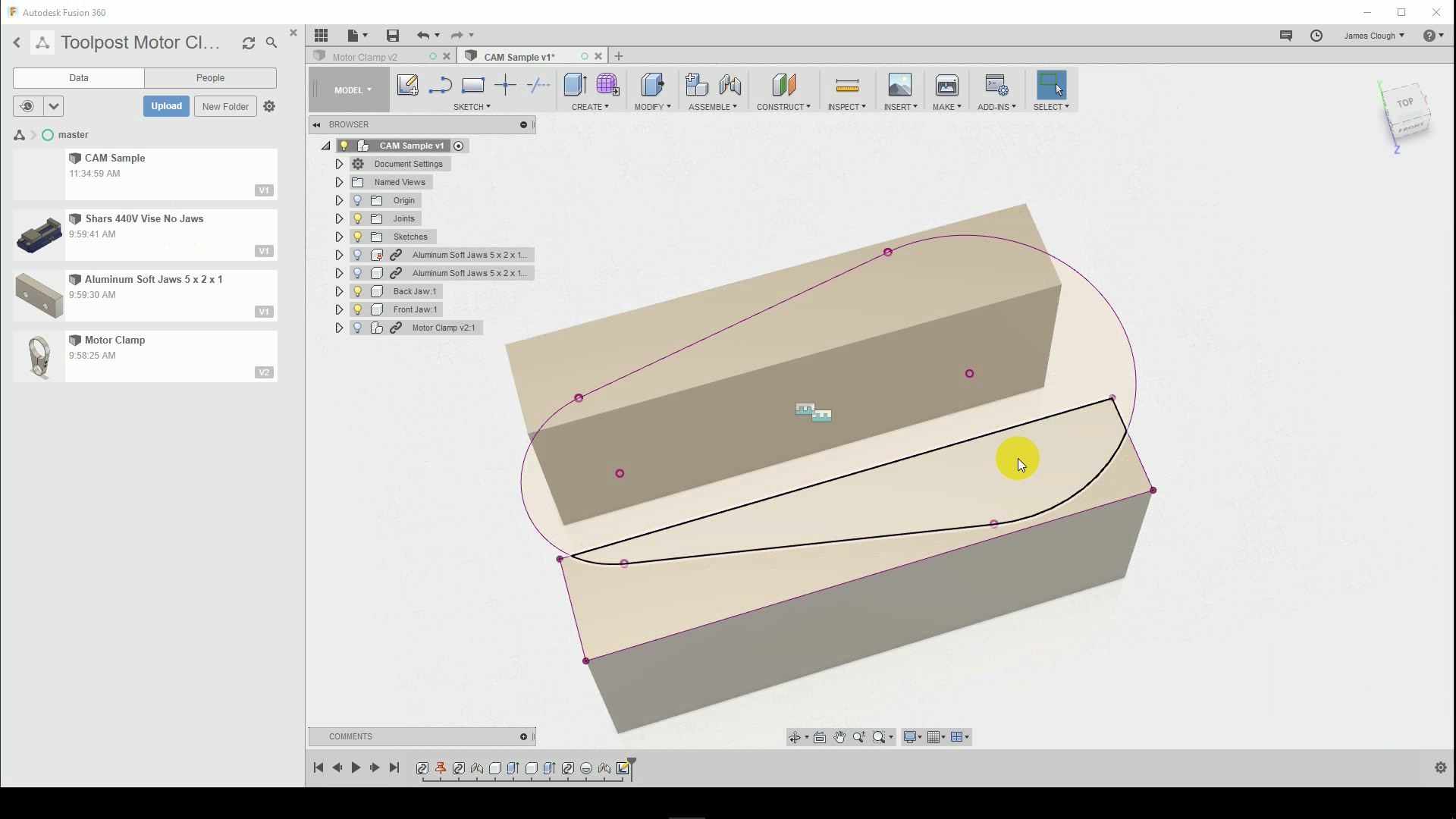
Once everything was positioned, I created a sketch on the top of the jaws and used the Project tool to transfer the edges of the part into the sketch. Because the sketch really only includes the contours of one of the jaws (a limitation of Fusion 360) I also projected the other jaw to create contours.
Once I had contours, I used the Extrude tool to cut material out of the tops of the jaws. Because I had the part already in place, I set the extrusion to use the “To Object” option to tie it to the part instead of entering a fixed distance.

Multiple Setups, Same Origin
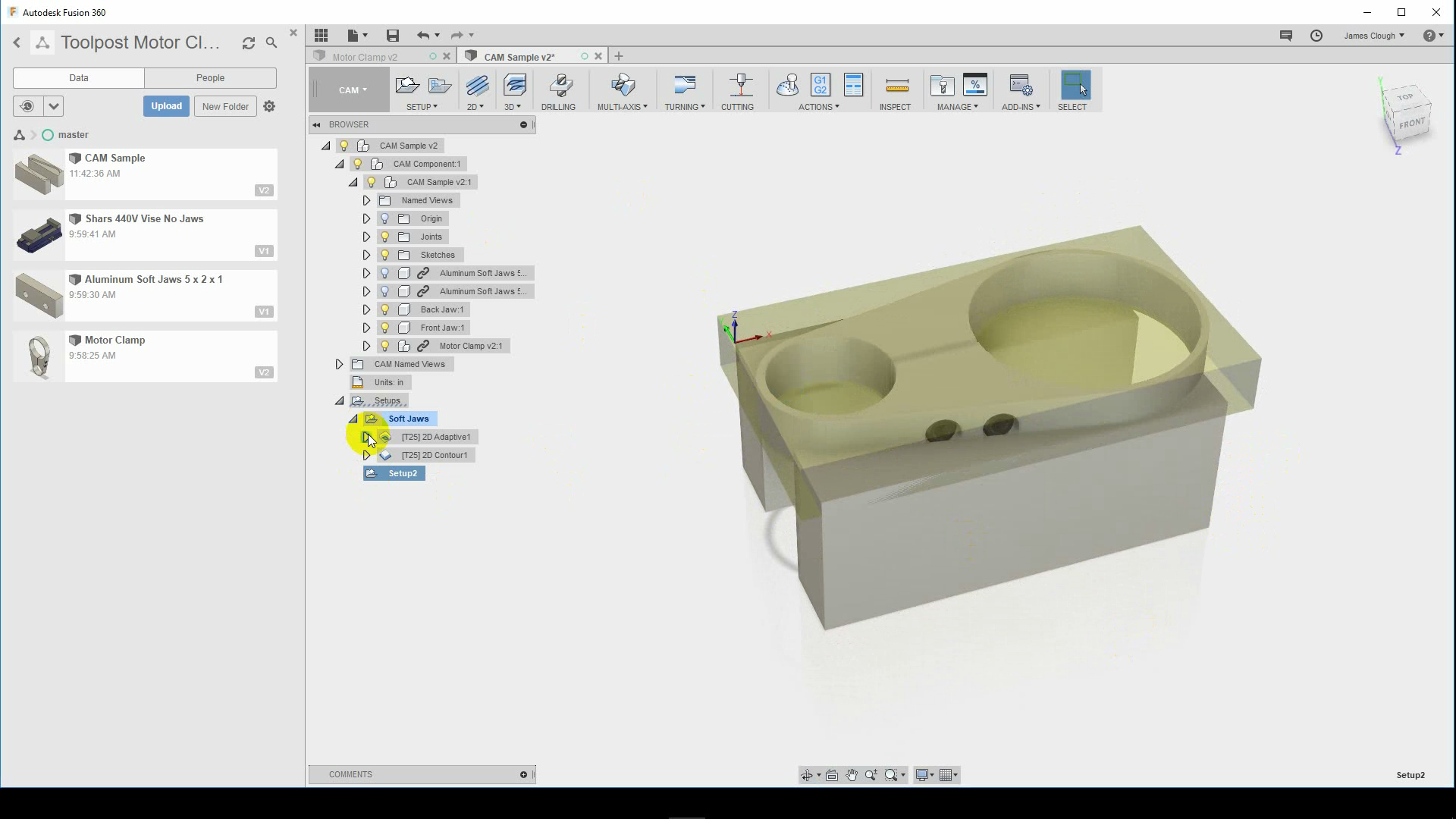
Once everything was modeled, I created two setups–one to carve the jaws and one to machine the part.
For the Jaw setup, I used my carved jaw bodies as the model and set the imported soft jaw blanks as the stock. For the part setup, I set the part as the model and the carved soft jaws as the fixture. Both setups have the origin set on the back, left corner of the back jaw. This allowed me to mill the soft jaws and then mill the part without changing the machine zero point. I used a parallel to space the jaws apart for milling and then removed the parallel and clamped the part for the rest of the machining operations.

Next Step: Clamping Bolts
This was just a quick interlude to cover something I missed in the original video. Many thanks to bostondan77 for the question. Next week we’ll get back to the machining and finish out the motor clamp.