This week we’re starting on the drawbar for the toolpost grinder. Since the spindle has an ER25 taper and a collet nut, it’s easy to hold mounted grinding points in collets, but we also want to be able to hold grinding wheels. To do this, we’ll make wheel arbors with an 8 degree taper to fit in the end of the spindle, and we’ll need a drawbar to hold them in place.
The Material
I decided to use W1 tool steel for the drawbar, simply because that’s what I had in stock. In retrospect, W1 was a terrible choice because it’s relatively difficult to turn on a small lathe and it threads terribly. It tends to tear out and leave a terrible surface finish when cut slowly (e.g. when threading). If I ever make another drawbar, I’ll probably use 1144 (Stressproof equivalent) or even 12L14 and make things easier on myself.
Turning Strategy
The drawbar represents a significant amount of mass spinning at high speed with the spindle. For this reason, it is important that it be as concentric as possible. This part would be a great candidate for turning between centers. Unfortunately, I don’t have any drive dogs at the moment, and I didn’t want to stop to make a set right now.
Instead, I used the 4-jaw chuck and a live center. This means that every time I changed the setup, I had to pull out the indicator again, but if I do it right, this process should still let me do all of the turning with .0005″ or less of total runout.
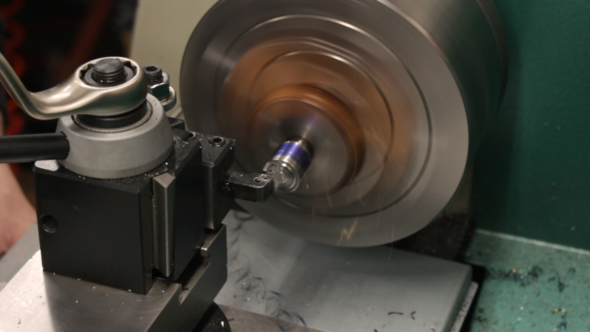
The first step was to face off one end of the stock and put in a center.
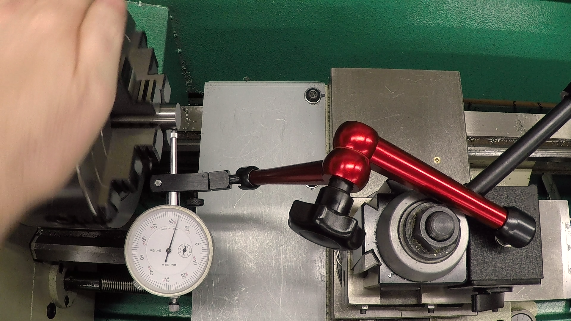
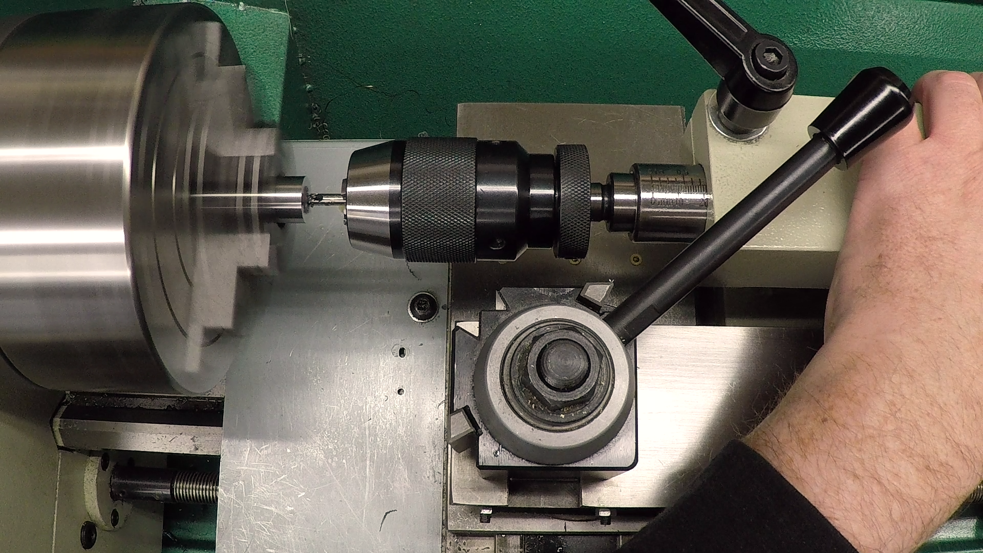
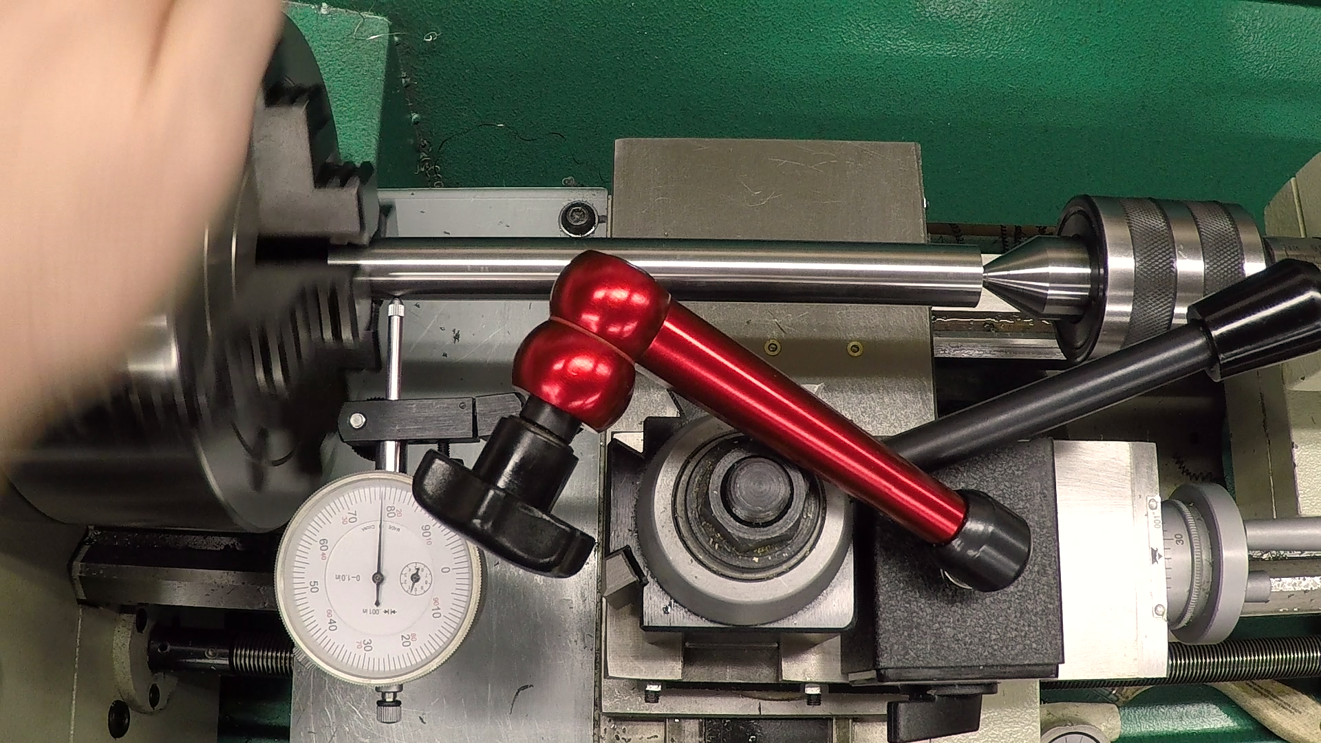
Once the end was faced, and center-drilled, I extended the stock out of the chuck, supported it with a live center and re-indicated it. After indicating, I pulled out the center and tapped the part around to get the free end running within a couple of thousandths. This isn’t critical, since the center will pull the part to the…uh…center. But having the part centered naturally reduces the stresses that could be released later, resulting in warping.
Forming the Body
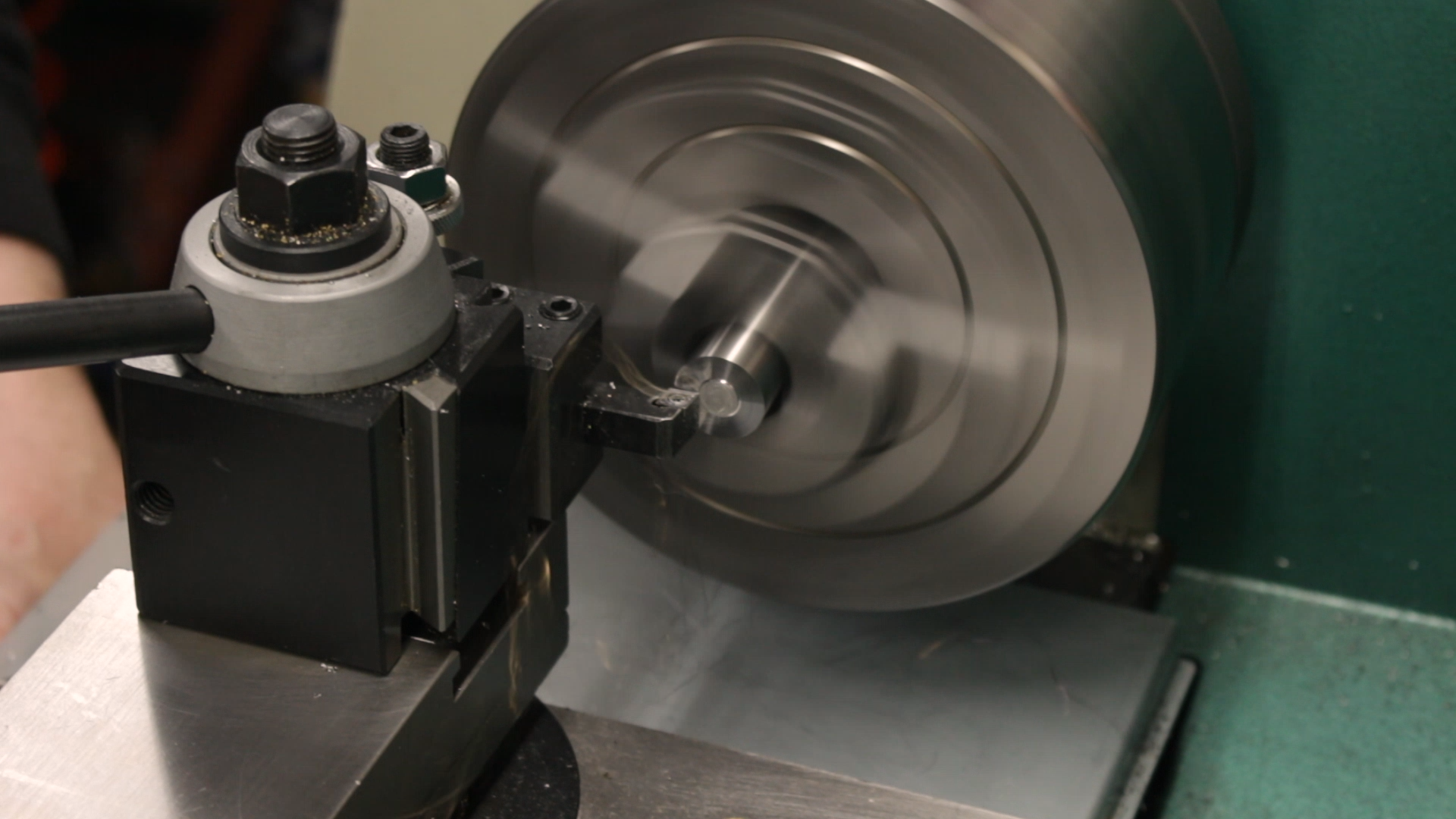
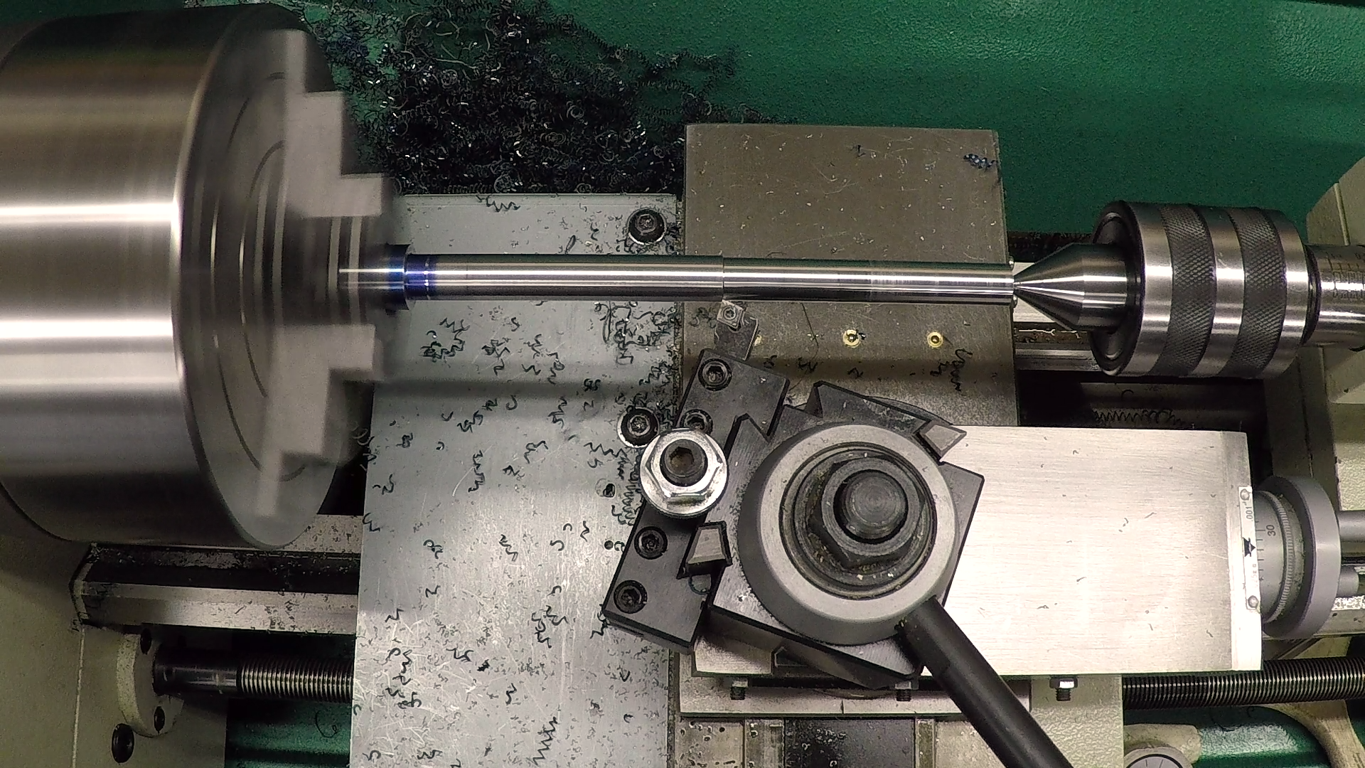
There are two diameters on the body. The first is the diameter of the register that fits in the end of the spindle. I started by turning the entire length of the drawbar to this diameter.
Confession time: this was a bit of a mess. I struggled for a while trying to find a cut recipe that would break the chips and still leave a good surface finish. What you see in the video is the third attempt. On the first, screwed up the threads. More on that next week. On the second, I overshot the diameter by enough to scrap the part. In retrospect, I could have just shifted up the stock a quarter inch and turned a new register, but I didn’t think about that until I had the third attempt complete.
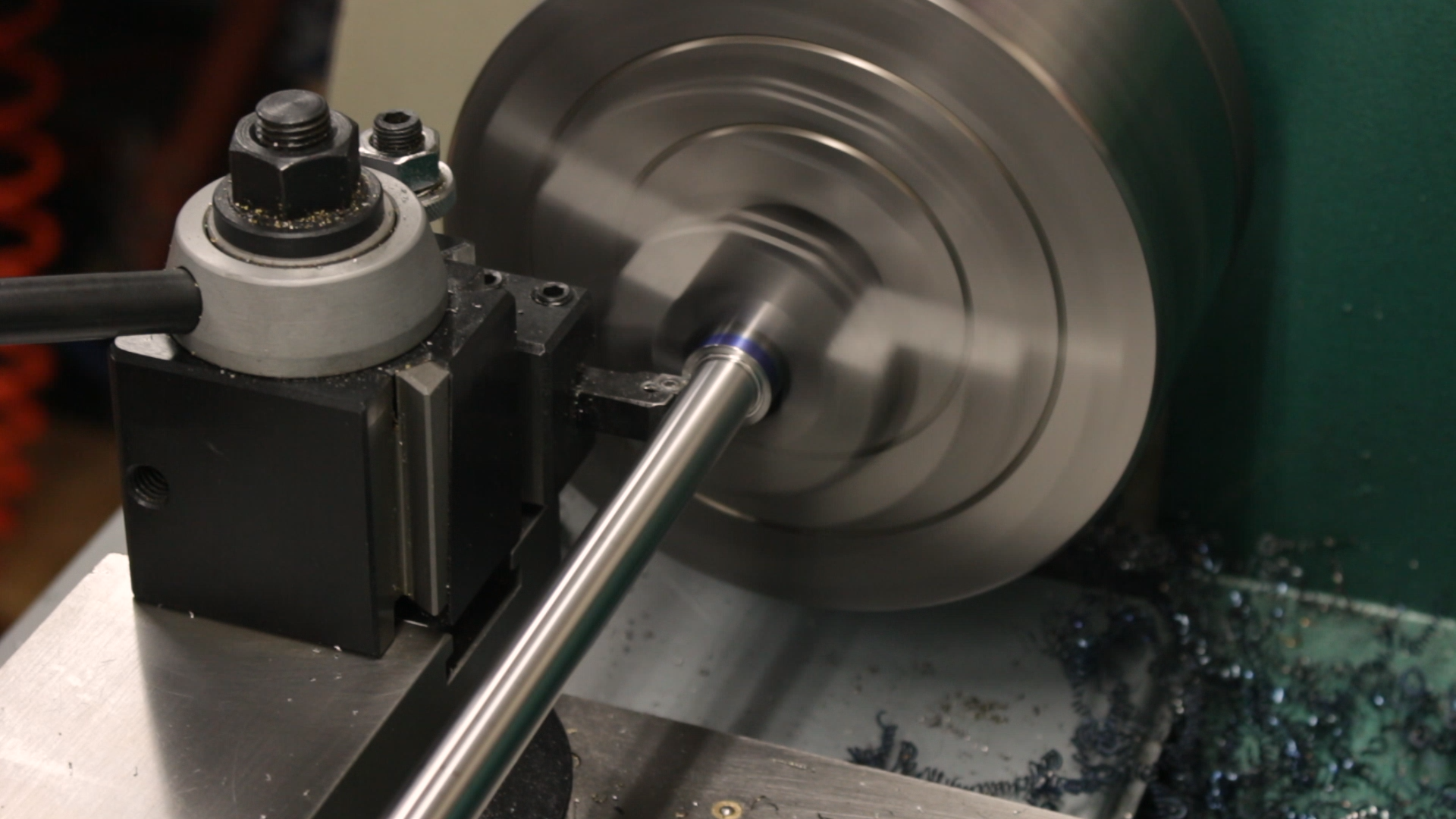
Note the long, curly chips in the photo above, and the nice, short chips breaking off neatly in the photo below. The difference is the lead angle of the tool. I turned the tool to lead by 20-30 degrees, and that’s the result. Of course, I could only do this because I wasn’t turning up to a 90 degree shoulder for this cut. I’ll keep this in mind for the future when I’m working with W1. It might even be worth making some new toolholders to use the obtuse corners of the CCMT inserts for turning.
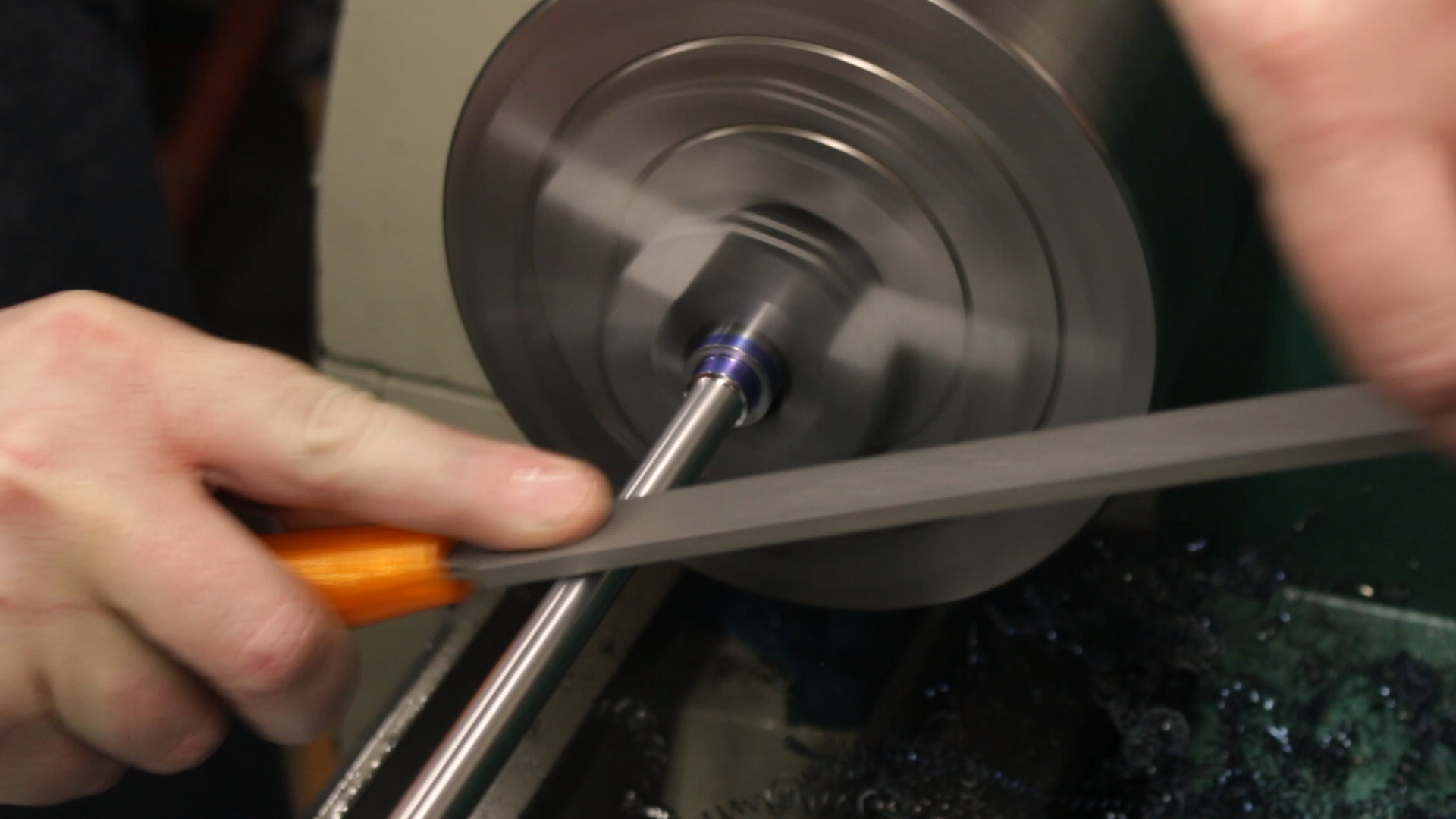
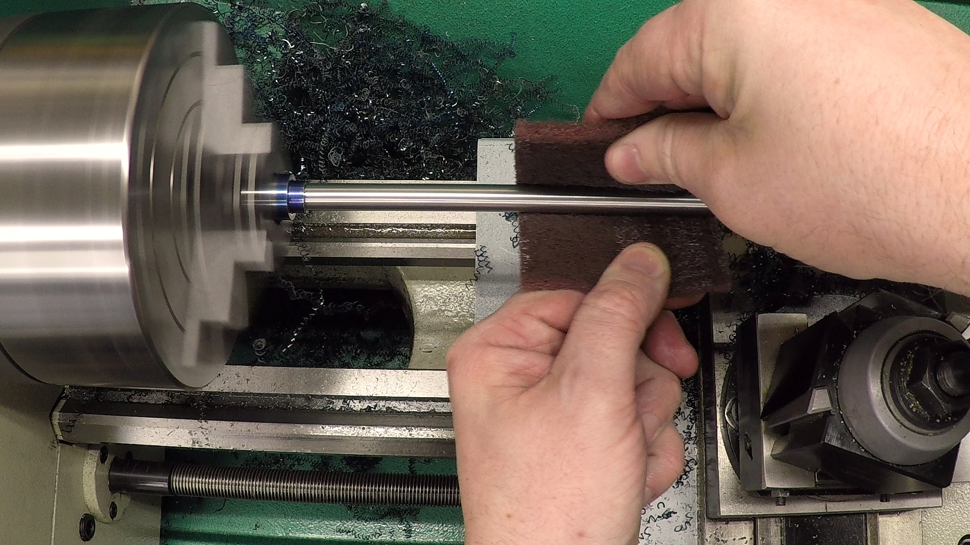
I took the last .001″ or so with a lathe file. At 2400RPM, it loaded up fast. Next time, I’ll probably slow down a bit for a better surface finish. After a little work with Scotch-Brite, though, the finish came out very nice.
Forming the Drawbar Head
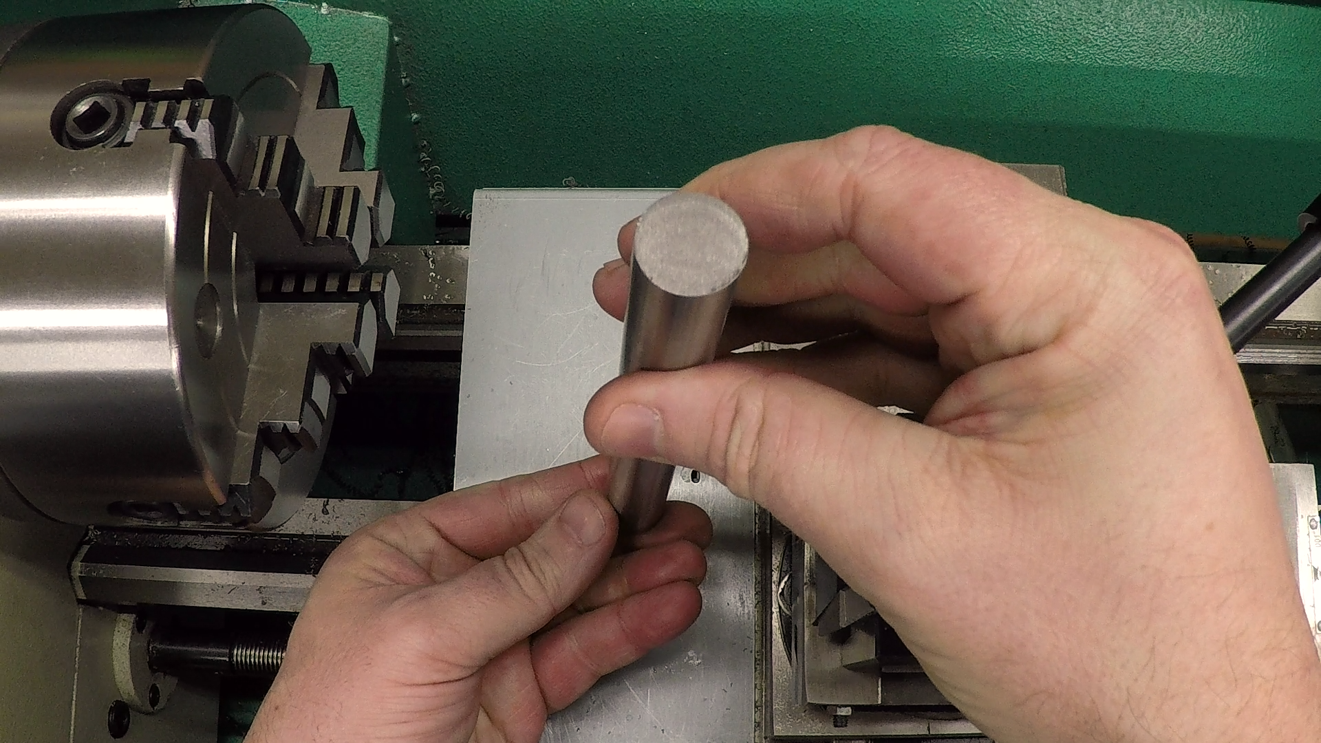
After forming the body, I flipped the drawbar around in the 4-jaw chuck and indicated it in again to work on the head. I faced it to thickness and put a chamfer on it, leaving it ready to go to the mill for flats.
As long as I had it centered up in the 4-jaw, I went ahead an popped a center in the end, just in case I want to do any work on it in the future. I have no plans, but it’s here if I need it. Plus, it now looks like I turned it between centers like a real machinist!


Next Steps
That’s it for this week. Next week we’ll flip the part again and single-point some threads before taking it to the mill to put on the flats.
If you’re following along with the build, here are some links to some of the tools used in the video:
*This site contains affiliate links for which I may be compensated
- Shars CCMT0602 RH turning tool holder (eBay*): https://goo.gl/Q1Jsdp
- iGaging 0-1″ Digital Micrometer (Amazon*): http://amzn.to/2EdYXZq
- ZLiveCenter 3MT triple ball bearing live center (eBay*): https://goo.gl/nE1u2o