 Maybe you just finished installing your new double extruder, and you’re not sure what to do next. Or maybe you have been playing with it for a while, and you just can’t get the nozzles to line up perfectly. You’ve come to the right place.
We’re going to walk through the procedure for calibrating your extruder so you get consistent results every time.
Before You Begin
- This method assumes you are using Auto-Bed-Leveling (ABL). If you are not, the method presented here for leveling the nozzles will not work. You will need to find a way to level the nozzles mechanically by using shims, adjusting the carriage mount or some other method.
- You should have your extruder offsets configured roughly in your firmware or slicing software. You can get approximate offsets by measuring. If you’re using the original Itty Bitty Double Extruder, the starting X offset is 20mm (plus or minus, depending on your extruder orientation) and the Y offset is 0mm. If you’re using the new Itty Bitty Double Flex extruder, the starting X offset is 27mm.
Download the calibration objects here:
Coarse Leveling
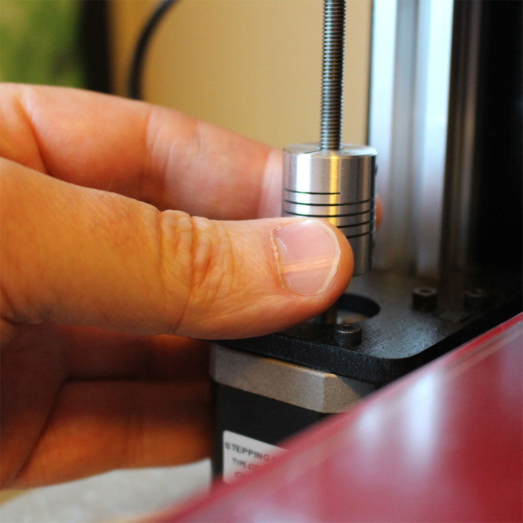
The first step is to get the nozzles approximately level. Do this by turning the Z axis motors by hand. Don’t worry if the X axis rods don’t end up level. We’re just trying to get the nozzles level, and we’ll let Auto-Bed-Leveling worry about the axis.
- Make sure the nozzles are clean, with no plastic stuck to the tip. You can heat the nozzles to temperature, and then wipe repeatedly with several layers of paper towels as the nozzles cool to make sure the bare metal is exposed at the tip.
- Center the X carriage over the bed.
- Cut two strips of paper and place them on the bed, underneath the two nozzles.
- With the power off, lower the X carriage; turn the Z motors by hand until the nozzles just touch the pieces of paper.
- Try to move the piece of paper under each nozzle. Both pieces of paper should lightly drag against its nozzle with about the same force.
- If the drag is not even, turn the Z axis screws in opposite directions until the nozzles are perfectly level and you feel the same amount of drag under each nozzle.

Your nozzles are now approximately level and you can move on to adjusting your Z offset.
Z Offset
Methods for adjusting your ABL Z offset vary by printer and firmware. You can usually adjust the value in the firmware, and you may be able to adjust it using the LCD panel on your printer.
- Adjust your Z offset so the Auto-Bed-Level cycle zeroes at the point where the nozzles just touch and you feel light drag against the paper.
Your height is now close, and you can move on to fine adjustment.
Fine Height Adjustment
 To perform fine adjustment of your nozzle heights, you will need to print one of the two-material height gauges included in the download, above. The files are provided in both STL and AMF.XML format. If your software supports it, use the AMF.XML files.
- Choose the height gauge that matches the first layer height of your printer. Gauges are provided for 0.2mm, 0.25mm, 0.35mm and 0.4mm. Check your slicing software for the correct height. Some printers (MakerFarm) are configured by default to have a different height for the first layer.
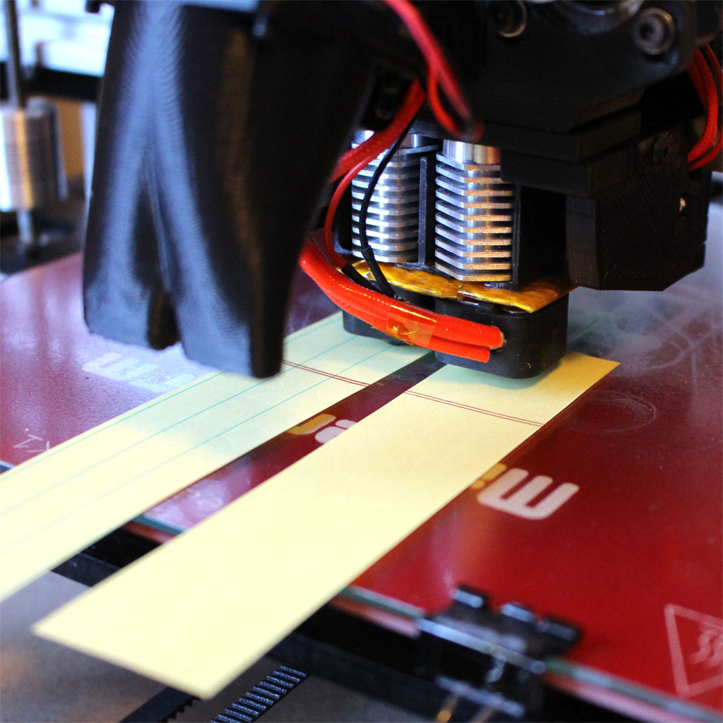
- Slice and print the height gauge as a two-material object.
- Let the print cool.
- Peel the objects off the bed and measure the thickness of each object with calipers. Both objects should be exactly the same thickness and should match your first layer height.
After printing and measuring the objects, make the appropriate adjustments:
- If the part printed by Extruder 1 is thicker, turn the Z screws by hand in opposite directions to lower Extruder 1 and raise Extruder 2 slightly.
- If the part printed by Extruder 2 is thicker, turn the Z screws by hand in opposite directions to lower Extruder 2 and raise Extruder 1 slightly.
- If both parts are too thick, increase your Z offset by the amount of the error.
- If both parts are too thin, decrease your Z offset by the amount of the error.
Print the object again to test your changes and repeat until the objects both come out with thickness matching your first layer height.
Extruder Offset Adjustment
The hard part is now done. Compared to the height adjustments, the horizontal alignment is easy. Just print and measure the alignment gauge and use the calculator to calculate your correct offsets.
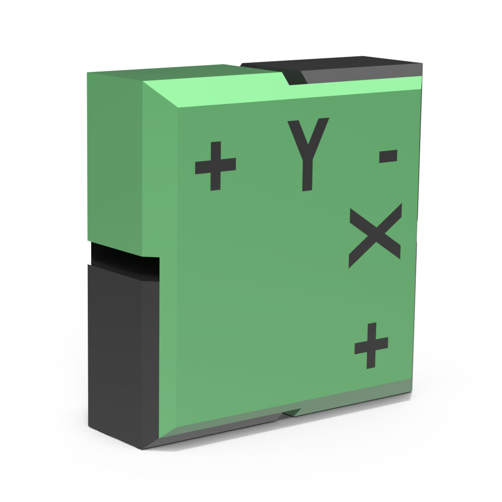
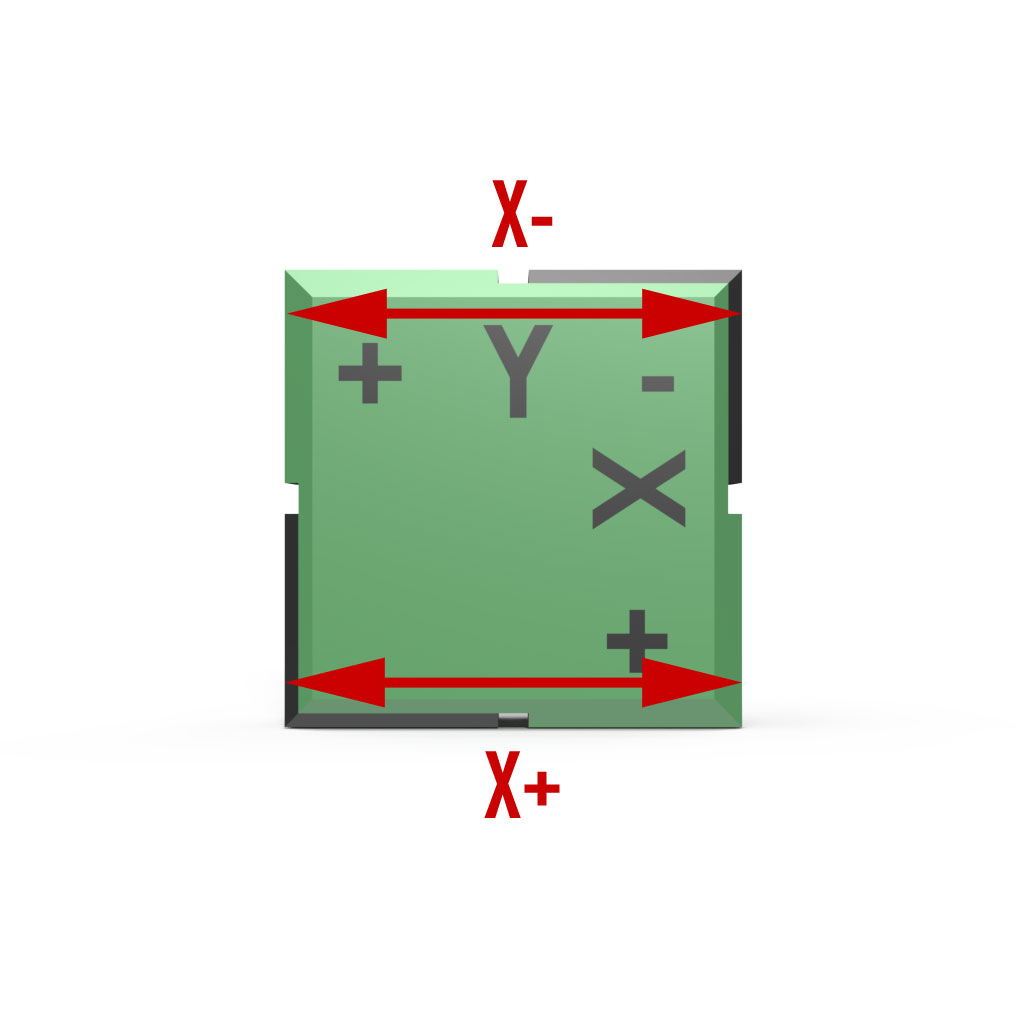
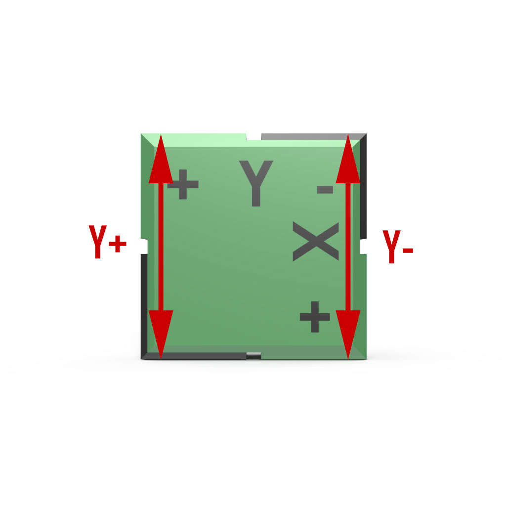
- Slice and print the two-material Alignment Gauge object and let it cool. Do not rotate the object when slicing. Make sure it is oriented as shown in the diagram, below.
- Use calipers to take measurements in the X and Y directions, at the + and – points, for a total of four measurements.
- Enter your measurements into the calculator below, along with your current Extruder 2 offsets, and let it calculate your new offsets.
- Enter the calculated Extruder 2 offsets into your software, and you should be ready to go.

If you like, you can print the Alignment Gauge again and verify that your extruder is now perfectly aligned.